
Build (in progress): Cosmos Sv2
Welcome to my build log please be aware that this is my daily driver of a PC and must be put back together after most of the steps in this build log also this build is not sponsored by anyone so I have no due dates for anything however I have set personal goals but some upgrades may be a long way off due to budgeting.
Table of Contents
(Some browsers do not support this feature. More info in FAQ.)
- Update #1 — Vlog #1
- Update #2 — Vlog #2
- Update #3 — Vlog #3
- Update #4 — Vlog #4
- Update #5
- Update #6
- Update #7
- Update #8
- Update #9
- Update #10
- Update #11
- Update #12
- Update #13
- Update #14
- Update #15
- Update #16
- Update #17
- Update #18
- Update #19
- Update #20
- Update #21
- Update #22
- Update #23
- Update #24
- Update #25
- Update #26
- Update #27
- Update #28
- Update #29
- Update #30
- Update #31
- Update #32
- Update #33
Update #1 June 9, 2014
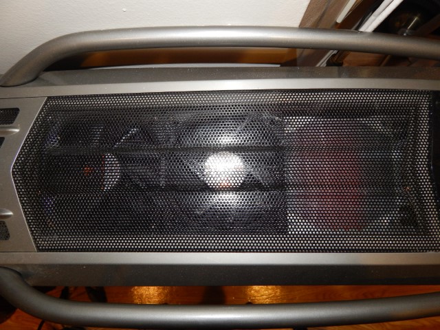
Long time ago back in 2008 I made one of my largest(literally) most expensive PC purchases and that was the $300 Cooler Master Cosmos S case. To this day I still see it as one of the most beautiful off the shelf cases out there hence the build/project. While I still see it as an amazing case it does lack in a lot of areas that modern cases strive in and almost make it easy to build a nice looking average pc in(no offence but it’s true with all the cable management stuff built into higher end cases). Where this case really falls short in is: Low amount of cable management, restrictive meshes, unpainted interior, no side window, I’m sure there’s more.
So here I am today 6 years later trying to make the Cosmos S relevant again, or at least make my system look better, hoping that CM will come out with a Cosmos S v2 or a Cosmos T or something.
Here’s some of the earliest pictures I could find of what the system used to look like in chronological order.(warning some of these may make you cringe)


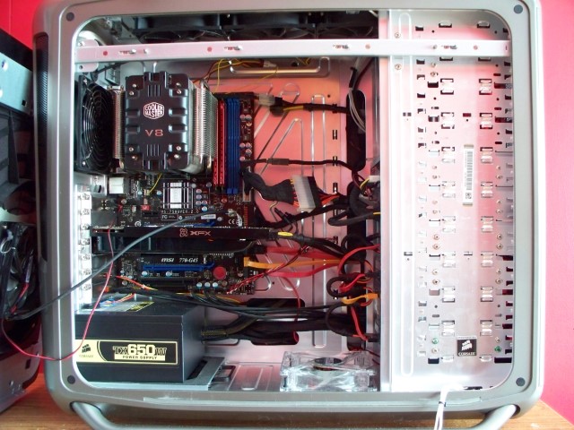

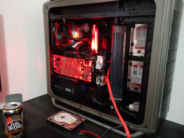
Here’s the Current Setup:
-CM Cosmos S
-Phenom II x6 1090T @ 4Ghz
-Corsair H100 push pull
-Asus Sabertooth 990FX
-16GB Patriot Memory
-XFX R7950 DD @ 1Ghz core, 1.35Ghz memory
-D-Link Wireless pci-e card
-AVerMedia TV pci card
-TP-Link Gigabit LAN pci-e card
-1x DVD RW, 1x Blu-Ray reader/DVD RW
-1x 300GB WD Caviar Black (main OS drive), 1x 1.5TB WD Caviar Green(game capture storage/scratch disk), 2x 2TB WD Red drives(main storage in raid 1 for redundancy)
-Corsair HX850
-Various Cougar fans
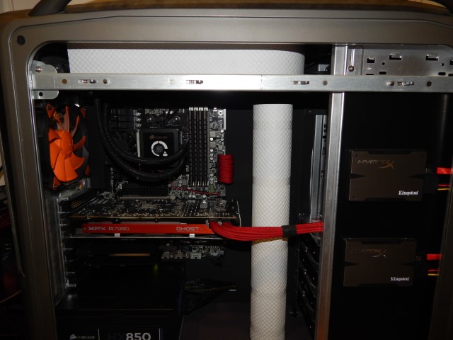
This is how it currently looks as of June 9, 2014


First thing to be done is removing those 2 optical drives to give the exterior a slightly better uniformed look which will also allow me to install 3x 120mm fans in the front of the case. Then up to the top cover to cut out the metal and plastic grills leaving only the mesh.

I was going to replace the mesh of my side panel with a glass insert. Well not being able to find a place that does custom flat sheet glass that was in my area I decided to settle with plexiglass (eww I know). So I took my side panel and headed down to my hardware store and bought a piece of plexi. Since I just needed a simple square piece cut I asked them if they would cut it and they said sure but the guy who knows how to operate their fancy saw wasn’t in yet. So they said if you leave the side panel and your number with us we can cut a piece of plexi to fit and call me when it’s done so I said sure since the cuts were free. As some of you who may have owned a Cosmos S in the past there are stand offs on the inside of the side panel to screw a plastic insert that held a 200mm fan and the modders mesh.
Well when they put the plexi panel in(which wasn’t even cut square) they decided to use the screws also even though there are clips that hold the plexi. So what happened is that the screws pushed against the aluminum of the side panel and caused a raised bump to show on the exterior of the side panel *facepalm*.
I talked with the manager to replace my side panel since they damaged it and they refused to since they can’t order via their in store system or something. So I asked to at least get a full sheet of plexi for free so I can do it properly myself, which I got.
It’s been about a week and I still haven’t replaced that badly cut piece of plexi since it is serving its purpose and won’t be seen once the case is closed. I added extra washers onto the screws so they no longer press against the aluminum.
The problem is that I still had those horrid bumps visible on the beautiful brushed aluminum. I found some matt black screws and cut the heads off with a hacksaw and contoured them with a dremel.
It turned out not too bad.

The screw heads are just held on with some very very thin “permanent” scotch double sided tape. Also the Cosmos S logo that was on the mesh was just too nice to not have on the side panel. Getting the logo off was a breeze since you can soak it in alcohol and just push on it through the mesh.
For the logo I used some reusable scotch double sided strips so that I could more easily relocate the badge somewhere if I needed.
All in all it turned out alright considering the mess ups. The screw heads match the raised badge and don’t look as out of place.

Well that’s all I got done for now I get off work early Wednesday so we’ll see what I can do then.
Update #2 June 10, 2014
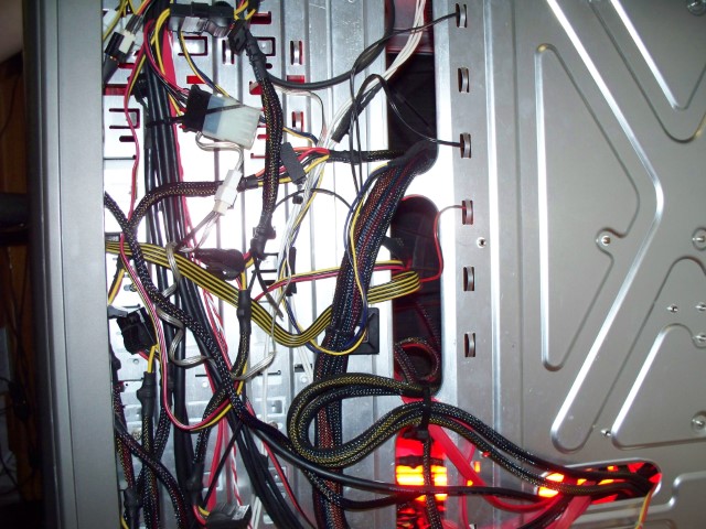
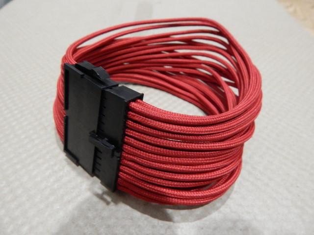
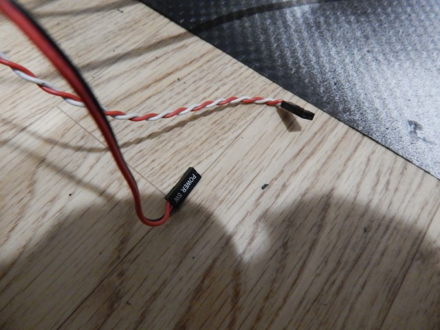
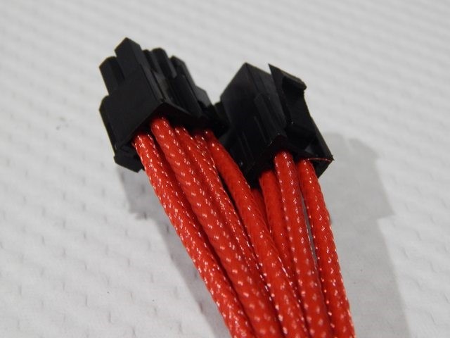
So got a bit of an update. After work I stopped by my local Canada Computers and picked up a new 24-pin extension. As some of you may know the Cosmos S has a touch sensitive power button which mine surprisingly(knock on wood) still works perfectly. However as you can see in my previous pics that the 24-pin extension looks horrid. Well here’s what I picked up:
So I’ll be splicing in the case power connector into this extension tomorrow.
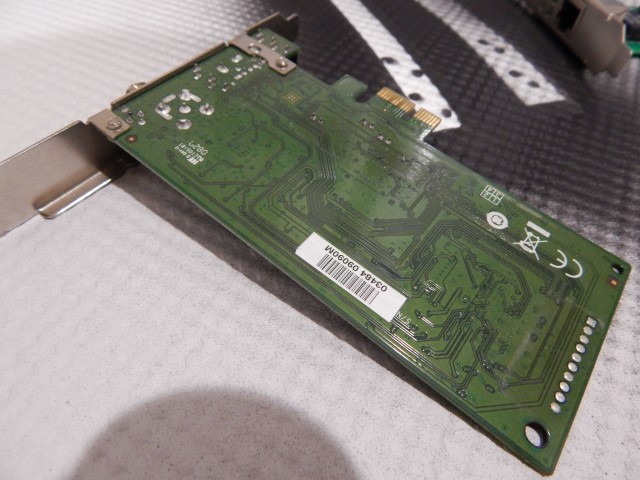
Also since I work with cars for my job I have easy access to Plasti Dip which is amazing. So I pulled my D-Link PCI wireless card to test out painting the back of it because I don’t really care if I kill it since I rarely use it. Plasti Dip says to let it dry for 4 hours before use so I’m gonna let it dry overnight.


So I’ll be painting this card tonight and if the Plasti Dip doesn’t kill it somehow which it shouldn’t I’ll be doing the same to my other green backed cards.
Update #3 June 11, 2014
Alright so I managed to get a bit of work done today on this and I’m pretty happy with what I was able to get done.
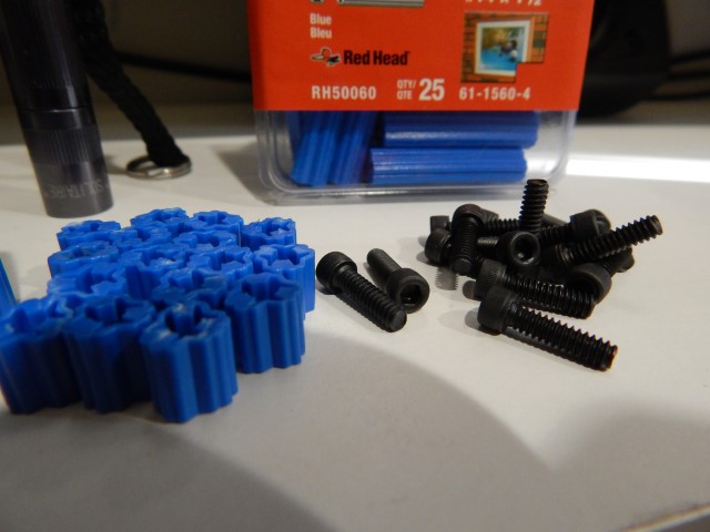
So I picked these up at work and I’m gonna try and use them for mounting my hard drives differently in the system. If you don’t know what they are they’re plastic concrete anchors which these are #14×1-1/2″ which work great as spacers/anchors for stuff in computers. Here I cut them down to the approx size I wanted to avoid the drive’s board shorting out on something. Also I got these really nice looking black 6-32 screws for mounting the hard drives, they use a hex head instead of the usual philips you see.
I slapped together that wireless card and tested it to make sure I didn’t mess it up and it works and looks way better than before. Oh also as note to anyone using plasti dip and masking areas off always have a super sharp knife with you. I tried to peel the tape off but it was pulling the plasti dip off the card too so I had to cut the plasti dip as I pulled the tape off.
It turned out pretty good looking for an experiment.

Since I was on a roll for painting with plsati dip I thought why not paint more stuff. Front panel connectors, a few more pci cards and a power supply should do.


I managed to source some vented PCI slot covers and well I’m not sure about them in the end the case is going to be neutral/slightly negative air pressure so I may have to find another solution for slot covers maybe plain Jane black non vented ones.

Also remember that 24 pin extension that looked horrid? Here’s a close up of it:
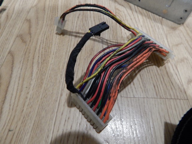
So if you ever wondered what Bitfenix alchemy cables look like underneath all that sleeving well it’s just plain black wire.

Splicing the case button power connector to the new extension was easy and taped down with lots of electrical tape to avoid the soldered splice from being damaged in any way and to hold the sleeving that I cut in place(that stuff frays like crazy after being cut and even after melting with a lighter) . Besides no one is ever gonna see this part of the extension in the finished build.
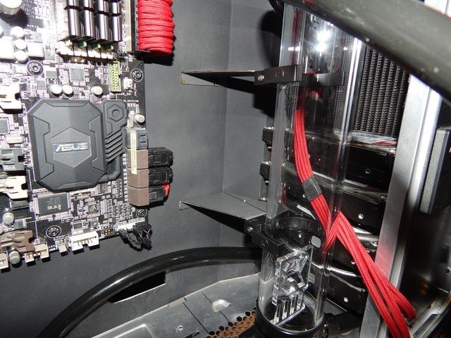
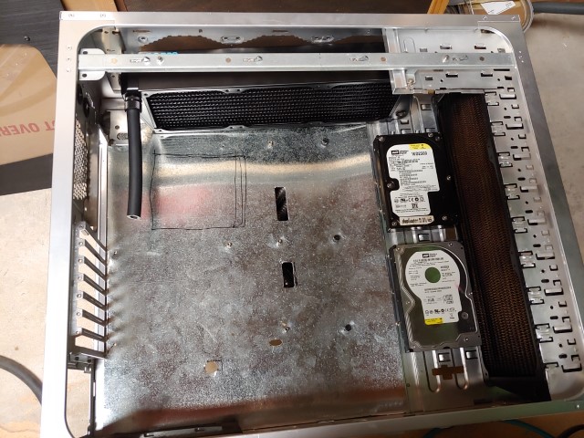
So for the final bit of this update is a roadblock I’ve hit in my plans. Originally I was going to mount the Hard drives vertically on the inside of the 5.25″ bays. Here’s a pic with a test fit drive to show how I was going to orient them but on the inside instead of where I’m holing it.
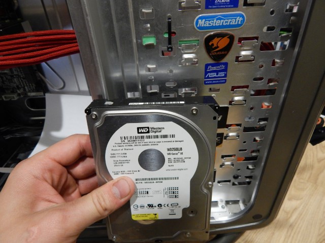
So a few problems with this: the cable management will still be horrible if you look through the side of the case from the rear. Also it seems less space efficient because I have to use spacers to avoid the tabs that usually hold the 5.25″ devices up. Also the holes that are already in the case for the 5.25″ bays don’t line up at all with the HDD holes and I wasn’t in the mood for drilling holes at the time. So those screws and plastic risers in my first pic will have their uses found somewhere else. I have an idea already for a new way of mounting the drives but that’s going to have to wait until at least the weekend because it requires a little more work than just slapping spacers on some screws. Also see if you can tell what other change is going to be included in the next update from that picture just above I know some of you have eagle eyes out there.
Update #4 June 14, 2014
Ok since the internet is being all crappy tonight it gives me a good excuse to work on my desktop so I will just leave this spoiler right here:
Update #5 June 16, 2014
Alright finally managed to get my pc up and running again no thanks to my terrible internet dc’ing all day when I just wanted my drivers :angry: . Anyways I did get quite a bit of progress(at least I think it’s a lot of progress) and upgraded some hardware so here we go.
Edit: warning lots of large pics
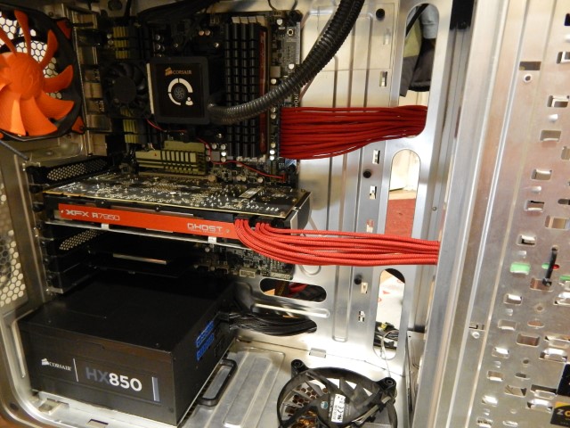
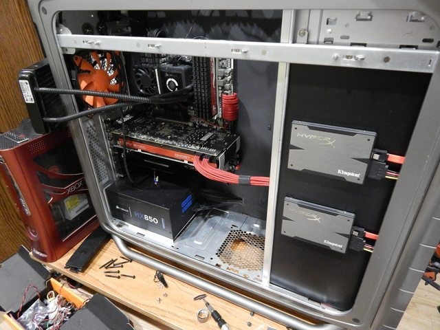
First off I apologize but I forgot to take pictures of the completed plasti dipped cables and pci cards but here’s what the cards look like in the system. As you can see..or not see they blend in really well with PSU.
I did however remember to take pictures of the sata cables I did since I didn’t like the white on them.
Before:
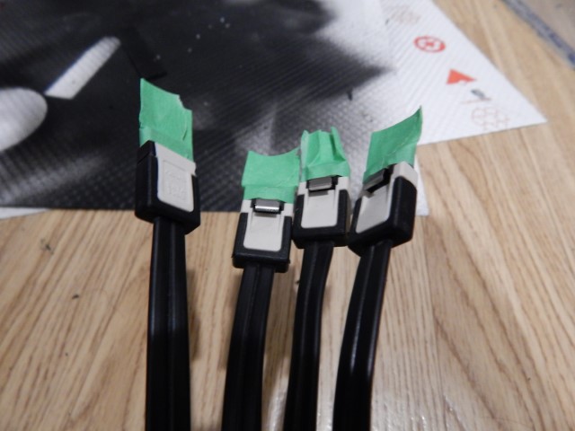
After:

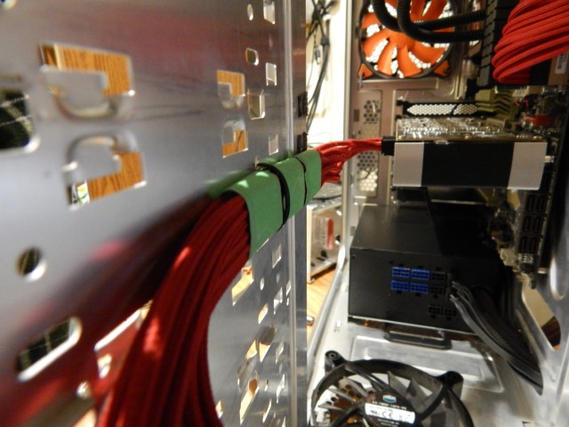
So I thought that the pci-e extensions looked pretty horrid going all the way down and across to behind the mobo tray. I figured it looked much better going straight across to the 5.25″ area so I grouped them up and tied it off then cut a hole in the back of the 5.25″ bays for the cables to pass into the cable management area of the case.

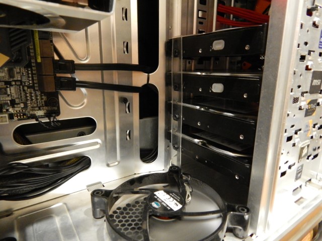
Alright next to address the issue of my hard drives. Since my previous plan failed I spent a good 30 mins while eating my pulled pork sammich thinking of how to mount these bulky hard drives. Well here’s something I thought of and learned why not mount them like all other case manufactures do with cables at the back of the mobo tray. While trying to fit the drive in sideways I learned a hard drive is approximately the same length as a 5.25″ bay is wide, bonus! So I marked things out and had 1 drive per 5.25″ bay allowing for better cooling for the drives and I doubt I will ever need more than 4 hard drives. So first off is cut some slots for the sata data and power cables(picture is blurry because I’m a bad camera man):


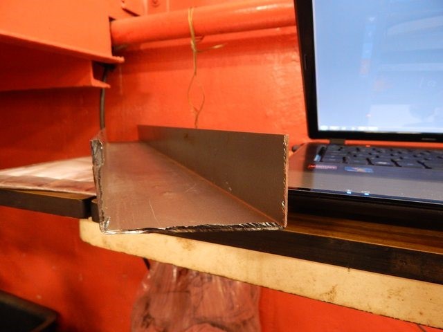
Next I needed something to hold the hard drives firmly in place so a short trip to my local Canadian Tire for some aluminum angle stock.
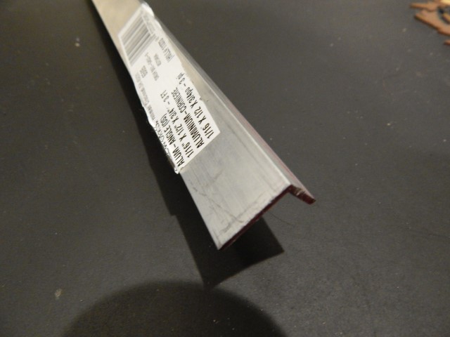
And of course foolish me tried to precisely drill holes with a dremel *facepalm* that failed and I wasted about 6″ of the stock. So I visited my mom’s(<3 you mom) where my drill press was and did a better job of making a bracket oh and I found something to address my front panel audio situation(more on that in another update).


I only had a piece of plexi for the visible bracket since I have plans for a custom bracket once I plan out my WC upgrade. Also the non connector side of the hard drives is resting on the 5.25″ drive bay tabs. So yes they are secure enough since this system isn’t being shipped anywhere.
Now that the drives have been cleaned up it’s time to hide those case badges that yes look horrible but at the time I didn’t have a windowed side panel so they were mostly hidden. I do have some sentimental value to them for some reason so time to hide them. Grabbed some plexi and cut to fit then remember those blue plastic risers from my older post? Well found a use for them and those screws.
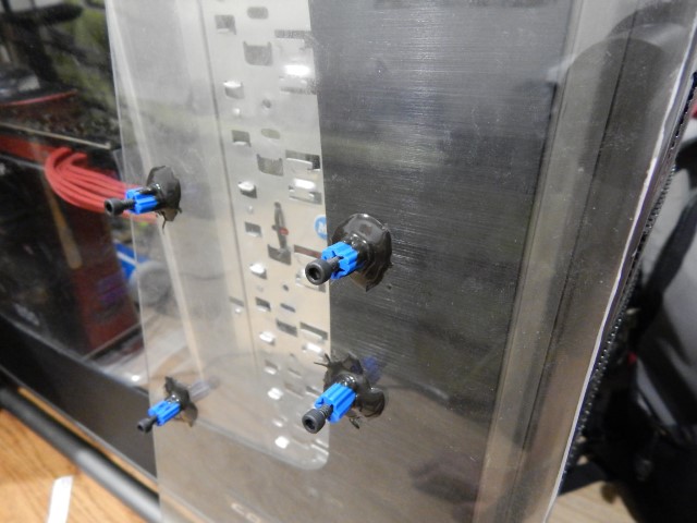

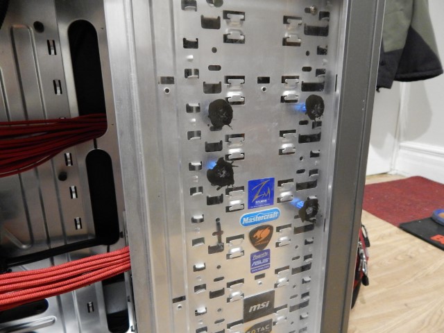
If you’re wondering what I used to glue those risers to the plexi it was trusty old J-B Kwik Weld.
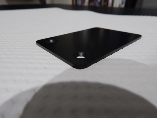
This was before I went out and bought the SSDs but here’s how I planned to mount them(logo is far off in the future of the build)

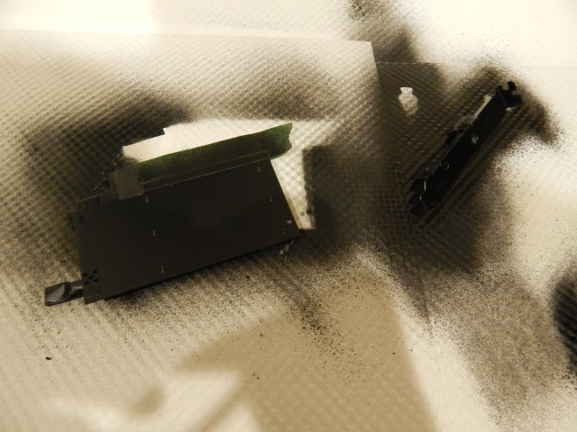
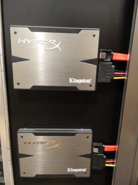
Used up the last of my plasti dip painting that stealth cover the result you may also notice I only have 4 mounting holes. Reason being if I ever plan to go back to a single SSD I won’t have unsightly holes in the stealth cover(points for thinking ahead right?).

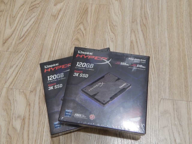
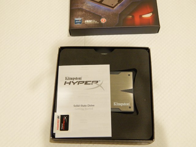
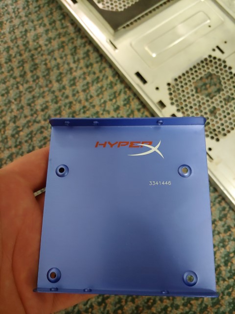
In the mean time waiting for that stealth cover to dry I unboxed those SSDs, those sexy sexy SSDs. I would’ve gone with Samsung’s but I’ve heard horror stories of their RMA process for Canadians and I’ve dealt with Kingston once before and it was a fairly easy RMA process if something did happen.


So no one makes the specific extensions I needed, most likely because it’s a very long custom length, so I made my own from some molex adapters and some wire.


Everything done and mounted.

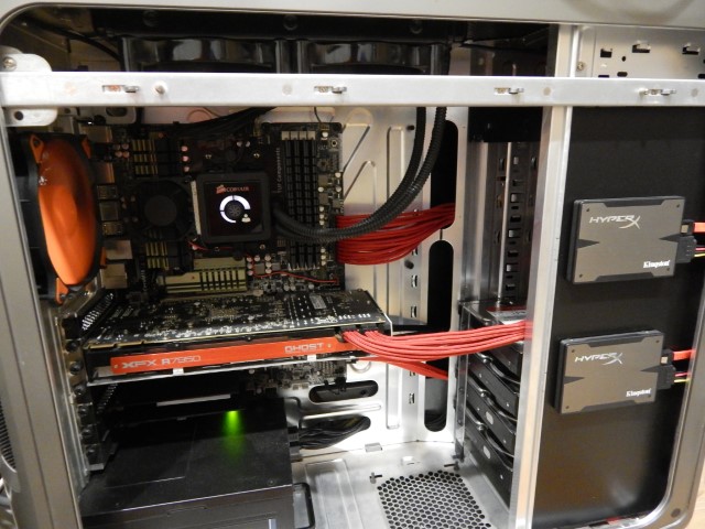
Well that’s all I got for now the next week or 2 is gonna be a little busy for me so I might not have any updates for a bit. Thanks for checking out my build.
Update #6 September 8, 2014
Hey long long long time no see. I apologize for my absence but you know how real life goes. Anyways my b-day is coming up on Tuesday and I decided to give myself a present this weekend which was spending 16 hours tearing apart my computer and rebuilding it again. Best b-day present ever…….I think. I literally just finished putting it together 20 mins ago and I’m currently writing this while on it and I hope it doesn’t mysteriously crash. Though the curing paint smell makes me wary.
So the challenges to overcome this time around:
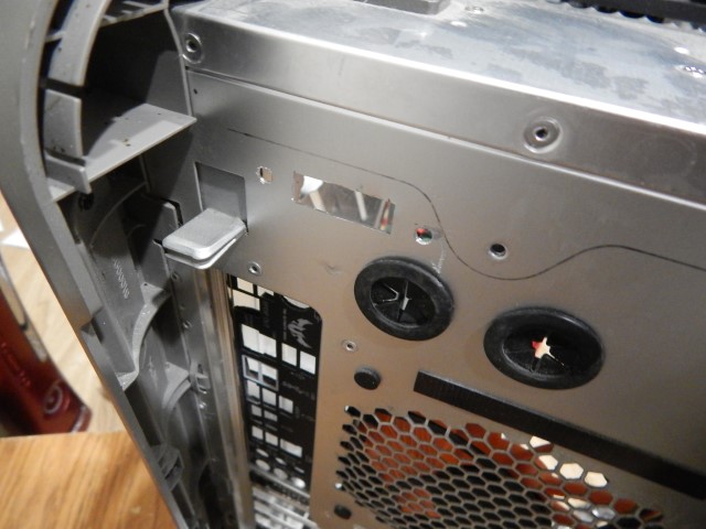
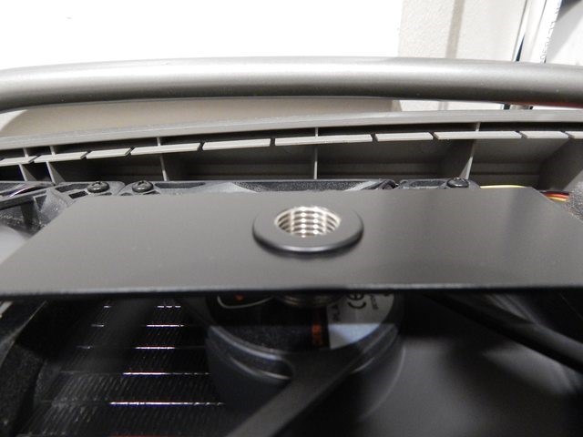
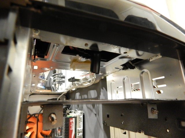
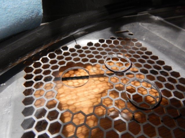
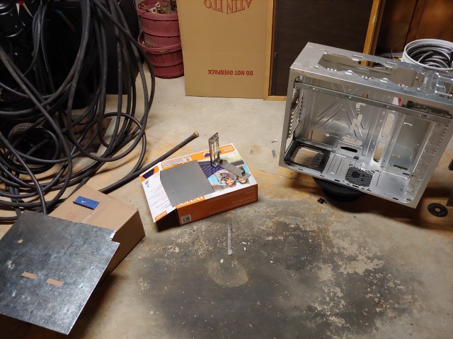
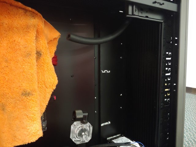
1: I plan on water cooling and I plan on mounting items on the bottom of the case I run into this issue:

As you can see the PSU filter is accessed from the inside of the case. While this is pretty convenient I wouldn’t be able to access it once the bottom of the case has something which makes me wonder why there was a fan mount there.
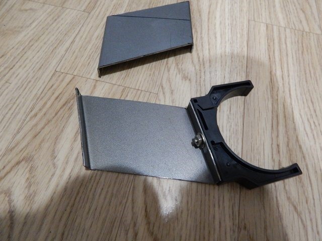
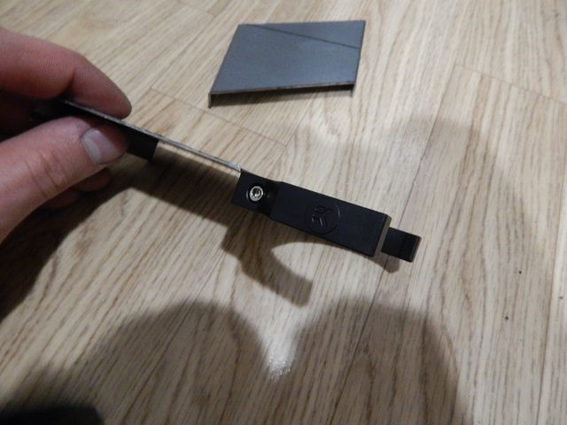
2: This is a kill 2 birds with one stone dealio. I almost never use my front panel I/O other than the power button and my headphone jack for splitting the game audio away from my music audio when I record game footage. So many of the cables from the I/O are unused and take up a ton of my cable management space. So I found this from an old comp I had:

It’s a separate front I/O of just the audio ports I truly lucked out that I had this and you can see what else I was planning by the aluminum angle stock I had cut that’s in the pic.
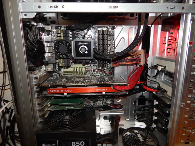
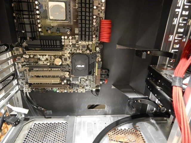
3: The terrible green on the motherboard heatsinks. You can see pictures of this in my previous post and yes they def don’t match the system and while I do plan on upgrading my cpu/mobo it’s not going to be until I get a custom water loop going.
4: Another 2 for 1! Tidy up the cables going to the motherboard even more and fix the terrible reinforcement bends in the mobo tray. As you may have seen in my previous pics my cables have to travel faaaaaaar from the cable management holes to reach my standard ATX motherboard.
5: Start planning for custom water cooling loop to replace 3yr old H100.
The Solutions:
1: So somehow I still have to make my PSU filter accessible when I install water cooling items. Why not copy what current cases do and make is accessible from under the case!
First stop Canadian Tire, ahh the store you love to hate or at least I love to hate. I picked up 4ft of U channel aluminum stock for about $6 so not too bad and I’m gonna have a ton extra for other stuff. I also bought a $4 can of flat black spray paint for things.
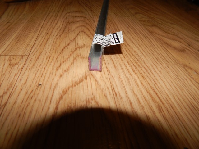
The PSU filter had some thin risers on it which I trimmed down with a box cutter knife so it would nicely fit in the U channel.
It fits nicely now to cut the aluminum to length.

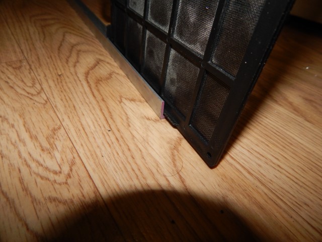
With some double sided tape magic I got those rails stuck to the bottom of the case. I also has to add a small piece of paper under the case feet mounts to help cover a bit of a gap between the filter and the case, I will have to find a more permanent solution in the future.


You’ll notice that it’s not coming out the back of the case and you’re probably thinking “You idiot! You’re just as bad as the guy who put it inside the case!” Well unfortunately the feet attachments are in the way of me being able to slide out the filter from the back which is probably why they put the filter inside the case in the first place. But I’ll take tipping over the case every once in a while to slide out that filter rather than no filter.
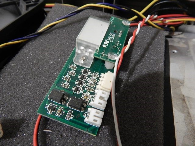
2: Oh those front panel cables I took it off which was easy only 2 screws. Turns out there’s 4 other screws underneath to access everything.

After popping that open I was pleasantly surprised turns out all those thick cables I wanted to get rid of are just extension cables and the PCB of the I/O is separate from the power button PCB. I promptly took those items out and was left with only 3 thin wires coming from the front panel, awesome more cable management room!


I will have to find something to fill this area with though.

Now for moving my headphone jack I used JB Kwik weld to stick those brackets I made to the small unit and cut a spot in the rear of the case. You can see I had a bit of an issue with drilling the holes to mount it. I blame my lack of a drill and drill bits.


That should work.
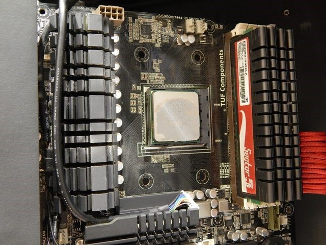
3: So before I got too far into the case I thought I should deal with the mobo heatsinks first since they will need time to dry.
The ugly:
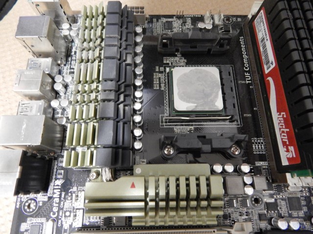

The less ugly(unfortunately you can still see some green on the MOSFET heatsink since I didn’t want to apply too many coats and missed it):

But wait that rear I/O still looks kinda ugly.

Glad I had the scotch tape there from the other pics. I guess that’ll do.
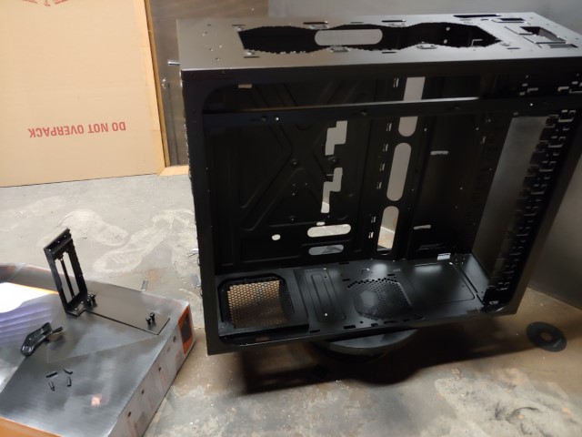
4: Yup obviously had to cut some holes so i marked up my case and started cutting.


Woah what the heck happened in that last pic? Well I went out and spent a whole $1 on a giant 22″x28″ bristol board sheet what was dark dark grey. Staples calls it black but it isn’t as you can see by the bottom piece which isn’t painted that I cut for a template to make a plexi insert. Anyways I measured my case internals and cut out a mobo tray cover spray painted it and put it in. I like it what do you guys think?
So nothing to do now other than throw everything together so I can use it to post this update.
Yea so my cable management isn’t the best but hey this time I didn’t have to almost stand on my sidepanel to get the thing to close.


Is it getting sexier and sexier or what. Please tell me what you guys think even if it’s bad or suggestions.
5: Alright I’m planning for water cooling(CPU only, GPU block not available) and have come up with a parts list. I’m hoping to be able to afford these items by the end of the year. I’m am new to custom water cooling so I would love suggestions on what you think of my parts selection but please remember I’m planning ahead so I’m wanting this WC loop ready to be able to have 1 maybe 2 GPUs pluged in when I upgrade my cpu, mobo, and gpu someday.
- http://www.frozencpu…tl=g30c107s1802
- http://www.frozencpu…l?tl=g30c95s161
- http://www.frozencpu…l?tl=g30c95s161
- http://www.frozencpu…c409s1612#blank
- http://www.frozencpu…O_-_Acetal.html
- http://www.frozencpu…8_-_Black_.html
- http://www.frozencpu…e_Sys_Prep.html
- http://www.frozencpu…voir_Strip.html
I’ve already test fit the part sizes in my case and they will fit with some kajigering. Mainly moving my bottom 2 hard drives up so my pump can fit underneath(I’m not going to have a fitting on top of the pump like my model shows). I also have about 1″ of space between the top rad and the top of the res if frozencpu’s installation height measurement of 400mm is correct.


Phew that was a long one thanks for checking out my build log.
Update #7 September 27, 2014
Ok so I got some good and bad news then some more bad news then a little more bad news and then some good news.
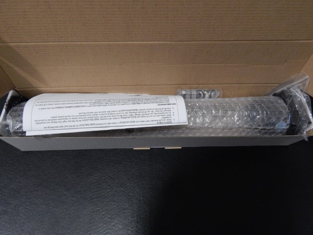
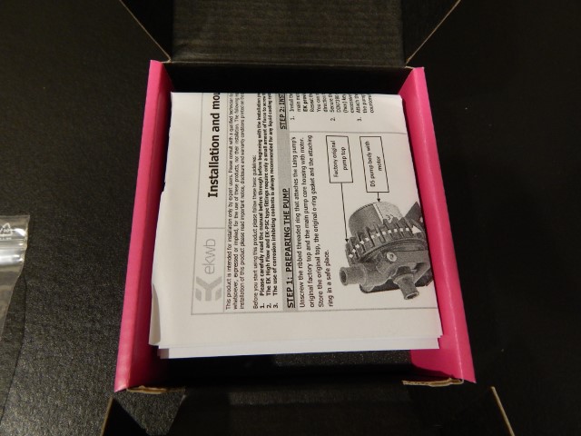
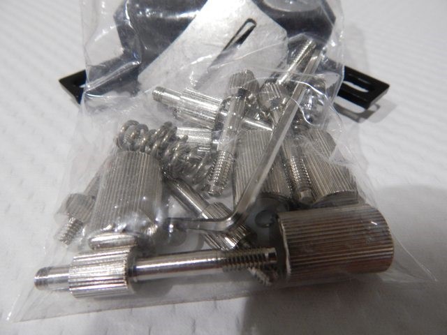
Good news is I received my parts from CMstore today(not sure why USPS and Canada Post decided to keep it at one of the furthest postal offices from me, I live closer to work than the post office it was at) got my trusty knife out and everything to get it opened.

Well I was kind of expecting my products to be somewhere in the middle of the box well apparently that’s not the case and this is how I opened it.

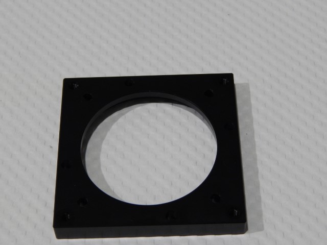
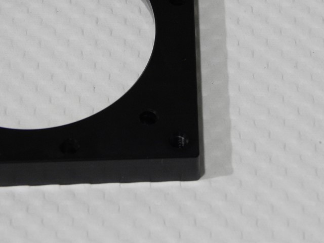
Well ok I thought they should be pretty sturdy products it’s not like they’re some delicate HDD or anything. Then here’s teh bad news I realized that one of the case drive bay covers I ordered isn’t a solid cover but an adapter instead *facepalm* that’s what I was trying to get rid of. Not to mention CMstore’s site shows the picture of a solid cover not an adapter.

It doesn’t end there if you notice and pay attention really close you”s see that the tabs on solid cover doesn’t look right. Well you’d be right they’re actually all broken. For those of you who don’t know the Cosmos S case these tabs on the cover help hold it straight against the case.

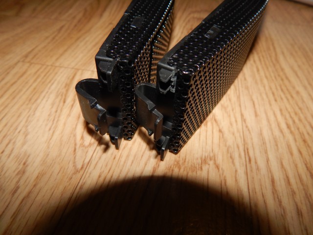
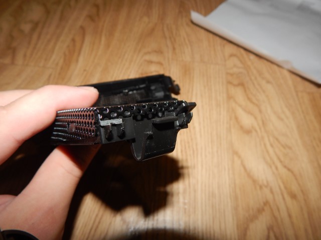
So yea that sucks I’ll have to wait until Monday to contact CMstore and see what they can do. I would basically need them to send me another cover that isn’t broken since I can make one proper cover out of the two I got. That one cover looks like it was kicked through a case breaking the tabs off so i don’t know how it got past quality control.
Alright the next amount of bad news remember that rear front I/O port I made? Well I don’t think anyone noticed but it was actually AC’97 but I knew that and my motherboard supports both AC’97 and HD Audio. Well it worked, the only problem is with AC’97 the ground goes to the case and well I guess I’m picking up some interference through mine which sucks. So when I ordered those covers I got a front I/O for another case that is HD audio. So that’s what you see in the 2nd and 3rd pics in this post.
Good news is that this product so far seems to work perfectly no more interference. I will have to desolder the USb ports off the pcb so I can mount my brackets to the same spots. Well I will update when I hear more from CMstore or if I take pictures of my current whole setup if you guys would like that let me know.
Update #8 October 15, 2014
It’s… Just… So… Beautiful…
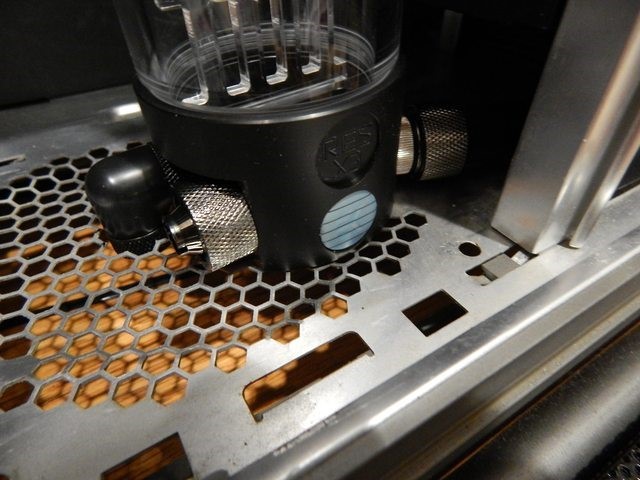
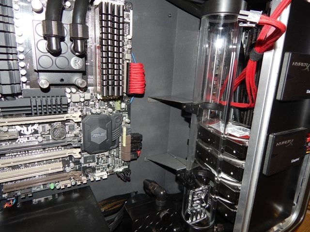
Hey guys what’s up so I got a bit of an update, I have started ordering my water cooling parts! First to arrive is the res and wow is it one beauty. Oddly enough it’s actually a little short even at 400mm I wish EK made a 450 res but a man can dream. I went with this res purely for looks and it seems it’s the only 400mm res I could find that has 3 side ports on the base. Gallery for that below.

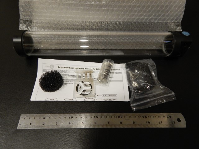
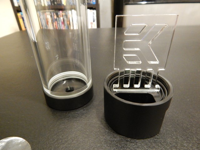

Mmm so nice. I absolutely can’t wait to get this upgrade started. Here it is in the case.


Ok and I finally got my new bay cover and well it’s damaged too so I guess that’s what I get for trying to get parts for a case so old.

Well I should be ordering more stuff soon so I’ll post an update then.
Update #9 October 17, 2014
Smaller update today but all my orders have been approved and now it’s just time to wait for the parts which should arrive middle of next week. Here’s the parts list with links to where I bought them:
- EK-Supremacy – Acetal Nickel (Model 2012) x1 (on order)
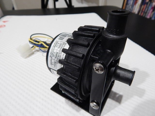
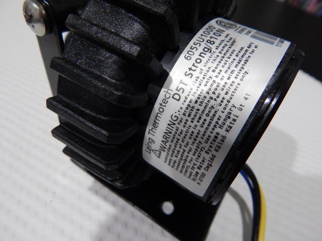
- DazMode STORM D5 VARIO 8-24V Pump w/TACH cable x1 (on order)
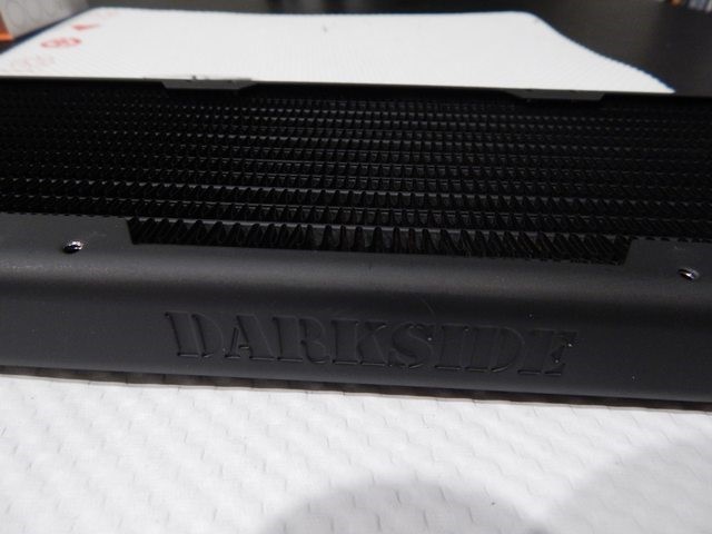
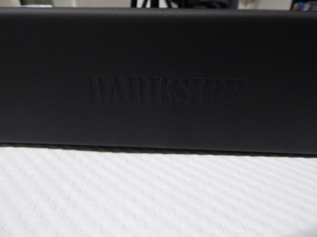
- Triple DarkSide Radiator – DS360-P x1 (on order)
- Triple LP360 Extra Slim Radiator x1 (on order)
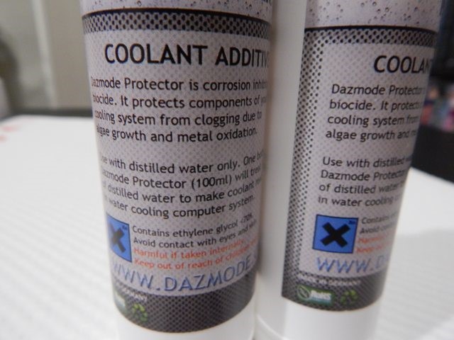
- DazMode Protector x2 (on order)
- 3/8″ID – 5/8″OD Straight Low Compression Fitting – Black Chrome x6 (on order)
- 90-degree Swivel Angled for 10mm x 16mm (3/8in x 5/8in) *Black* x7 (on order)
- Clear G1/4″ Crystal Stop Fitting III V2 x1 (on order)
- 1/2″ (12mm) DarkSide High Density Cable Sleeving – Jet Black 1Ft x10 (on order)
- 4+4 EPS 12″ (30cm) HSL DarkSide Single Braid Cable – Red UV x1 (on order)
- Compact Fill Port / Drain Port Valve – Nickel x1 (on order)
- G1/4″ Crystal Lighting Stop Fitting Module W/ 3PIN Wired LED -WHITE x2 (on order)
- G1/4″ 90 Degree G1/4″ Adapter – Black x2 (on order)
- Fill/Drain Port Sealing Plug w/ 3/8″ID Tubing Barb – Black Spark x1 (on order)
- 8mm Spacer Extender Adapter – G1/4 Male/Female – Matt Black x2 (on order)
- 8mm Spacer Extender Adapter – G1/4 Female/Female – Matt Black x1 (on order)
- 3/8″ ID Tubing – 90 Degree, Rotary Barb w/ Clamp – BLACK x1 (on order)
- Feser Tube UV Hose – 3/8″ ID – 1/2″ OD – BLACK / UV Blue (1′) x1 (on order)
- 3/8″” ID Tubing – Barb – Black Chrome x1 (on order)
- Replacement O-ring for Standard G1/4. Fittings – BLACK x10 (on order)
- PrimoChill PRIMOFLEX™ Advanced LRT™ Onyx Black 3/8 ID 5/8 OD Tubing (10FT) x2 (on order)
- Ek Water Blocks EK-RES x3 400 820ML Water Cooling Tube Reservoir X2 G1/4 Extenders X4 G1/4 Plugs x1 (Arrived)
- EK D5 X-Top Acetal Pump Top CSQ – Laing D5 & Swiftech MCP-650/655 (EK-D5 X-TOP CSQ – Acetal) x1 (Arrived)
Current total for parts including shipping and taxes is $838.39cad
Update #10 October 18, 2014
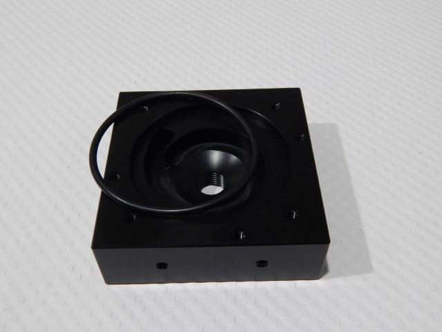
Hello hello everyone, got another small update and a bonus! Received my D5 pump top today and yup it looks pretty nice too. I know people like to hate on EK sometimes but I personally love their aesthetics and they couldn’t be all that bad otherwise they’d be out of business by now. Also I was experimenting with my camera a bit and you may notice some pictures come out way better than others. Anyways here it goes.
This is how FrozenCPU packs their pump tops(top of packaging in box was taken out in the picture) which is acceptable since the top is in its own box as well.


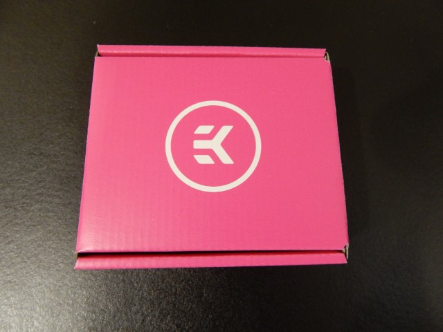
This is one super pink internal box which oddly I really like the look of.

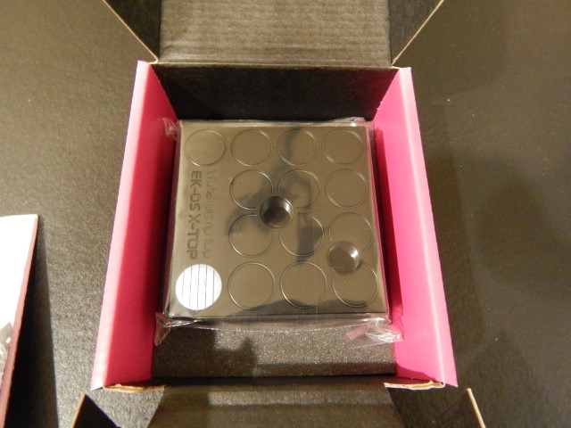


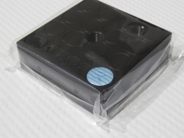

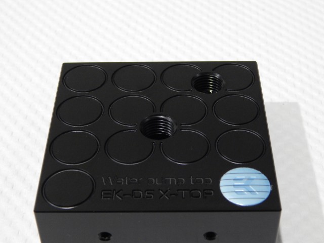
Gah! Already got a fingerprint on the thing.


That pump top will look great and of course match with the EK res I already have. Originally I was going to move up my bottoms 2 hard drives and place the pump under them but now that I think of it the pump would look great right beside the res which brings me to the bonus I made a vlog? Yea I think you call them vlogs and I explain it a bit there and of course I’m only human and I was trying to spit out a lot so it’s not very professional.
As I say in the video I originally planned to put the pump in the 5.25″ bays but I think it looks great right here. Also I was planning on painting a piece of plexi to replace the thin bristol board but after placing a clear temporary piece under the pump and res I think it would look great if I kept it clear and just plasti-dipped the bristol board under the plexi. What are your thoughts?


Update #11 October 22, 2014
I got my parts last night and it turns out my CPU block is missing the backplate and backplate gasket not sure how that happened but it’ll delay my progress a bit if I can’t get one for this weekend which I probably can’t because of processing times and shipping(I’m at work when they deliver mail, it would be so much easier if I could just pick it up but oh well) so I’ll spend this weekend experimenting with my point and shoot camera to try and take better pics of what I do have so keep an eye out for that update. I’ll probably do leak testing tonight to make sure nothing is leaking like my rads, res, or pump top, or my cpu block. Wouldn’t be too good going through the process of trying to get a replacement backplate only to have the cpu block be leaky too.
Edit: Daz is going to find the missing parts tomorrow so there’s a small possibility of some work done this weekend we’ll see.
Update #12 October 26, 2014
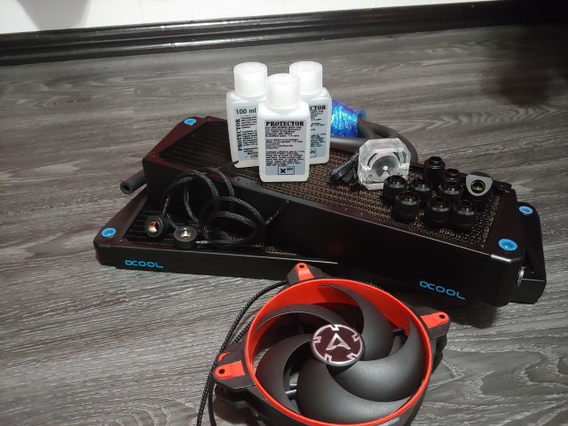
Alright managed to get some work done this weekend. I also got all my parts in order mostly so time to share some pictures and progress. I did make a couple mistakes and stuff which I’ll be fixing soon.
Here’s all the parts of my latest order and well it’s my largest single purchase of computer parts yet:


I like this Darkside extension however it does look very plasticy and while it does look nice it’s too shiny and doesn’t match my current BitFenix extensions which has a more fabric looking sleeving which I find looks nicer imo.
This DazMode coolant is pretty much straight glycol making it clear and perfect to add dyes like food coloring but I’ll be keeping mine clear.
Ok so the pump I ordered was the D5 Vario which has speed settings 1-5 and well I got the D5 Strong which is the standard non-variable speed D5 pump so I have to sort this out DazMode(be fair stuff happens) and will update you via a review on how it goes. Regardless I don’t really mind having the D5 Strong which is basically the eact same as the Vario at setting 4.5ish which is probably what I would have had the Vario set at anyways will just be a little harder bleading out air not being able to change the rpm on the pump easily.

These rads though they look very nice and the 360 slim one is actually very slim just slightly thicker than a 25mm fan which is perfect for the space I have which is minimal in the front of my case. Also you can see in the pictures the holes are offset from the channels of the rad meaning if your screws are a little bit too long they won’t puncture the channels of your rad making it leak. The screws would simply damage a few fins, still not ideal, but better than having your rad leak.

This thick rad on the other hand isn’t as ease of use as the 360 slim. If you use screws that are too long here there is a small possibility of puncturing the channels of it but there are small metal stoppers to help prevent this. I’m gonna use this rad in the top of the case, I think it will fill it in nicely.
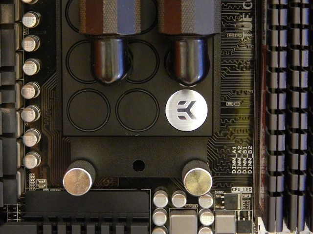
Ok here’s the CPU block and yes I do now have the backplates it’s supposed to come with so I got that resolved with DazMode. Not to mention this will match the pump top and the res nicely.

Fittings, wonderful wonderful fittings.

I think I bought everything I needed and yes they don’t match but I don’t have the money to get all matching ones but I would love to get proper fittings someday to make the build look really nice but that will come at a later date.

Now to my big but little mod. This took me pretty much all Sunday and well I think it turned out alright. This is what my front panel looked like when I removed the I/O pcb and well it’s pretty empty. I need to resolve this and make use of this space on the case.
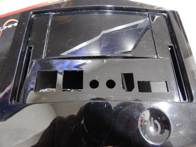
Well let’s take it apart:

It really pained me to do this but I don’t think this case would be around much longer anyways so I had to do this.

Well the last pic looked pretty dirty and I cleaned it up a bit plus cus some space in part that I need to hold the power button.
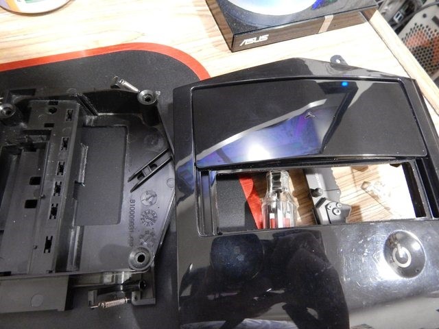
The power button:
While I was at it I marked the spot on the case that i will eventually need to cut as well.

The HDD light is something I still wanted to keep as well so I needed to keep the plastic part for the LED but get rid of the others for the front I/O.

More cuts and installed the LED holder.

Now to fill in that rectangle I cut out of my case.


Yup that’ll work and now it’s painted and waiting to dry on top of my running PC.
So while I waited for that part to dry I needed to do some more work on other things. This took me about an hour -.- but I think in the end it will be worth it. I bought 2 white LED plugs and well they don’t fit into the bottom of the EK res because EK thought it would be a great idea to recess the ports on the bottom but not make the recessed part big enough for even some normal plugs. So what I had to do is file down the sides of the LED plugs I got because they wouldn’t fit into the res to seal with the O-ring. This is what I ended up with which is pretty much perfect for what I need. The plug still sticks out a little bit so that I can grip onto it with pliers and tighten it properly. Also it provides something i can someone use to make sure the bottom of the res doesn’t slide around. Reason I’m doing this is that I want light coming up from the bottom of the res to light up the EK plexi baffle. Not sure how this will actually look but we’ll see. Worse come to worse I’ll just not run LEDs to the plugs.


After I delt with the res plugs I started to reassemble the front panel and this is what the underside looks like. But really it doesn’t look like that touch sensitive button should even work it’s almost like magic.

And here it is I did make a bit of a mistake which I’ll have to fix later with some plasti-dip. As you can see on the power button that’s lit up it seems that I’ve scratched some of the black plastic off on the inside and you can see the marks lit up now 😦 so I’ll do that when I cut the spot open in the metal part of the case.


So that’s it for now I tried it out and it seems I’ll have to get a T fitting and another red LED plug for the fill port because it actually looks really nice to have a light coming through that fill port since I have a crystal stopper in it. I’ll get a red one to match the power button. Hopefully I’ll be able to get the water cooling set up next time I do an update so we’ll see how it goes and I’ll also post an update when I receive word about the pump which if I can I’ll probably keep the Strong and not bother getting it swapped and just get the $6-$7 difference refunded as store credit. I could use that to get my T fitting and maybe LEDs for the inside of the case.
P.S. yes I will clean off all those horrible fingerprints on the front panel.
Update #13 November 2, 2014
Vlog #3
That vlog was uploaded late since it takes a long long time for me to edit and upload a video on my aging laptop but at least it’s up. The build is getting there I finally got myself a custom water cooled CPU. Yea yea I know there’s still a lot to do and what I have is overkill for just a CPU but oh man the results are so worth it. I still need to do things which I think I may make a check list at the end of this big update.
First up is that I needed pass-through ports for my res so I put my res in the approximate spot and started cutting luckily it sat right over the old fan vent so no dremel needed.
Originally I cut it very very tight and I’m not sure why since I will have something to cover it anyways.

So after that I decided to pull out my ageing H100 rad and plop the new top Darkside top rad I planned to use which I hopped would fit.

Here you can also see me test fitting the fill port clearance with a short piece of tubing to make sure it would clear the cut in the case I made and not hit the top bar brace.
Well it fits now the question is if the res will fit under it with the fill port fitting I have on top of it as well.

Huge fin spacing on this rad which I considered running passively which I may still do.

Very ghetto but effective stealthing of my D5 pump. I use run of the mill electrical tape and put it around the housing as I didn’t want to spend another ~$30 to get an EK housing for the pump and Daz doesn’t carry them anyways, so electrical tape it is!

Now I bought 10ft of 12mm black sleeving but I really could’ve just got 1 foot(I plan on experimenting with the remainder). I used it to sleeve a small portion of the 3 wires and again Electrical tape to the rescue. I have heatshrink at work but that would require me to go out and go back to work again after coming home so I just use tape which looks ok and isn’t in an obviously visible spot anyways.


Well I decided to put fans in anyways which the only ones I had 3 of are my blue BitFenix ones. I simply pulled out the LED bridge in them and they get hidden pretty nice since they’re a very dark blue.

So I had to find a way to make the res more secure. I know I will never be shipping this thing to anyone else but I do think I would like to take it to a lan event someday which means I would have to transport it in a car and having a res just sitting there with no support wouldn’t go over too well I don’t think even if I drove as carefully as possible. So onto the adventure of finding a way to secure the res without having it right on the motherboard tray like a lot of people tend to do with these types of side clamp brackets. So it just so happens while I was going through the scrap metal at work I found some that would work nicely and oddly enough was only 2mm short of being the perfect size so good enough. This is a piece I cut off as they were about 6 feet long and I think someone else took the rest anyways.
Here is the semi final result. I won’t paint them yet, I’ll wait until I paint the whole case. They are cut to the proper size though and work like a charm.

That doesn’t look too bad even without being painted.
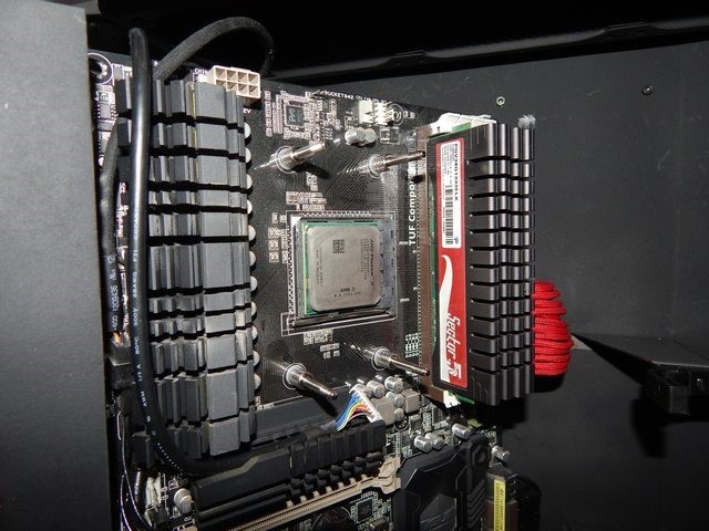
Time to remove that stock mount from the Sabertooth. That thermal spread isn’t too bad either could’ve been better though.


Pretty sure this is how you do it, I didn’t read the instructions ![]() but anyways I put the backplate with rubber isolator on and posts with washers to hold it in. Then proceeded to put the block on tightening in an X pattern. pretty simple stuff but I guess if people haven’t done this before I can understand it being a little daunting. Anyways got it all mounted and the board back in place, meaning time to add one thing to that list of stuff to do; make CPU cutout.
but anyways I put the backplate with rubber isolator on and posts with washers to hold it in. Then proceeded to put the block on tightening in an X pattern. pretty simple stuff but I guess if people haven’t done this before I can understand it being a little daunting. Anyways got it all mounted and the board back in place, meaning time to add one thing to that list of stuff to do; make CPU cutout.

Mmmm sexy.


It’s hard to tell in this picture but the plexi bottom is there I was lining up the holes to cut out on it. I realized this after running some of my tubing that I would eventually have to do that.
This is where I tried to make the holes as tight as possible since this is the visible part of the bottom plate. I didn’t use any measuring tools I just kinda eye balled it and it just so happened to work.
Still not sure if I will keep the plexi clear and have a black underside what i might end up doing and what i wish is what I did for the front panel in the first place is paint the underside only and have the unpainted side up I think that would solve my trapped dirt issue with many of the later pics. I’ll have to do that when I take it apart again to paint the entire case. I still think it looks pretty nice though.

Here’s my drain port on the under side of the case.

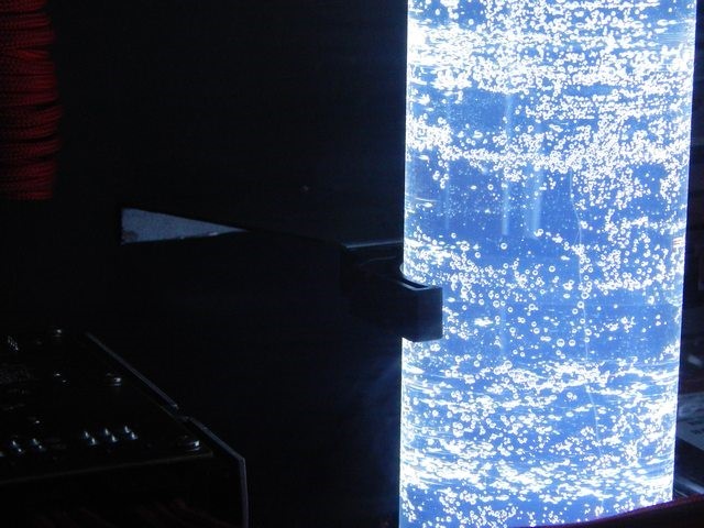
Here’s an example of the trapped dust issue. This is also when I started filling my loop and bleeding it for some reason it’s very blue in all my pictures and videos but it mostly white when seen in person not to mention the bubbles don’t help with the color either.

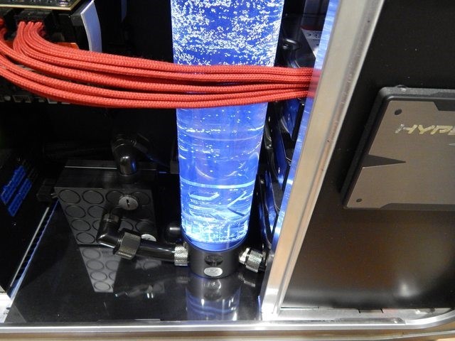
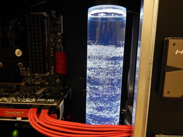
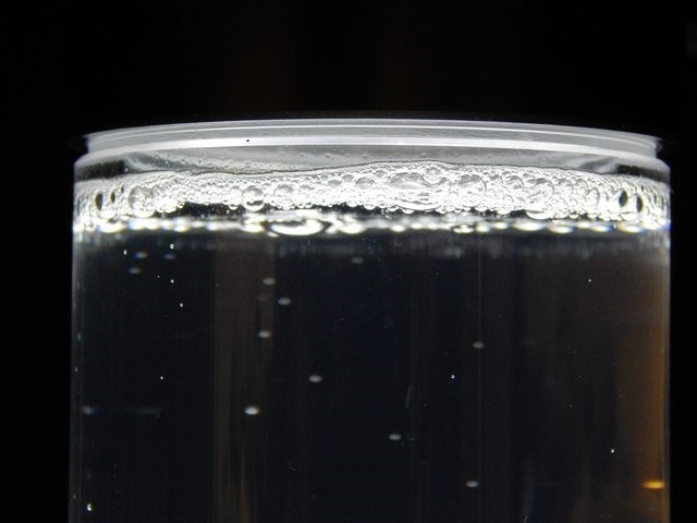
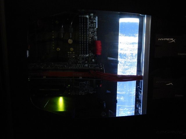
The night time glow, I expect this to dim as the bubble dissipate because those bubbles will be bending light in all directions making it look brighter than usual. I’ll update later with pics once all the bubbles get out of the res.

All in all my tower is still pretty light only weighs 60lbs totally easy for lan events!

Well that’s it, I hope you all like it there’s things I still need to do mainly: cut out a path for tubes to CPU block, fix bottom plexi plate, redo paint on front panel(easy cus of plasti-dip hooray), CPU cutout, paint the case etc etc. So there’s still work to be done meaning this build is far from being done but at least it’s mostly done. It’ll be several months until I can afford to get other upgrades(water cooled GPU for example) and stuff but I hope to get enough funds and time together to get the case painted in the next few months along with the other minor modifications. Until the next update!
Update #14 March 25, 2019
Wow it’s been more than 4 years since I have worked on this project. All I can say is that after update #13 I got comfortable and complacent with what I had. Well, fast forward 4 years and the aging components of this system were becoming clearly evident as I was having issues running games in settings that I wanted to run in and I was unable to record any game play at any decent setting. Well here we are 4 years later and I decided it is time to upgrade my main rig which will hopefully last me another 4-5 years without being too obsolete. So onto the parts, if you prefer you can visit the PCPartPicker list here: https://ca.pcpartpicker.com/user/NotSoEpicMods/saved/LYysZL
The old system(as of update #13):
CPU: AMD Phenom II x6 1090T
Motherboard: Asus Sabertooth 990FX rev1.0
RAM: 16GB Patriot Sector 5 @ 1337MHz
GPU: XFX HD 7950 1Ghz Core, 1.35GHz Mem
Case: Modded Cosmos S (Cosmos Sv2)
Storage: 2x HyperX 3K 120GB SSD raid 0, 2x WD Red 2TB raid 1, WD Green 1.5TB, WB Black 300GB
PSU: Corsair HX850
Display(s): 2x Asus 23″
Cooling: Custom Loop: 360 thick rad, 360 thin rad, EK res/pump top/block(cpu only)
Keyboard: Logitech G110
Mouse: Corsair M95
Sound: Oboard with Logitech something or other 5.1 speakers and Corsair Headset
OS: Win 7 Ultimate
The new system:
CPU: Intel Core i9 9900k @5.1GHz
Motherboard: Asus Prime Z390-A
RAM: 32GB Corsair Vengence RGB Pro @ 3000MHz
GPU: Asus GeForce RTX 2080 Ti 11GB Turbo
Case: Modded Cosmos S (Cosmos Sv2)
Storage: 2x WD Red 2TB raid 1, WD Green 1.5TB, WB Black 300GB, Samsung 970 Evo 500 GB M.2-2280 SSD
PSU: Corsair HX850
Display(s): Samsung 32″ 2560×1440 144Hz, LG 29″ 2560×1080 75Hz Ultrawide
Cooling: Custom Loop: 360 thick rad, 360 thin rad, EK res/pump top/block(cpu only)
Keyboard: Corsair K95 Platinum
Mouse: Corsair Dark Core
Sound: Oboard with Logitech speakers and HyperX Cloud II Headset
OS: Win 10 Pro

Now it’s just building for the next update.
Update #15 March 29, 2019
As you can see I had originally decided to go with another Ultrawide monitor however I had a few issues with the one pictured above which were mainly nit picky on my part. First, is that the ultrawide monitor is not curved and after having used this 34″ Ultrawide I can honestly say in a desktop setting a curved Ultrawide with the way to go. Second, you might be able to see a re 360 console hiding behind those parts. Yes, yes, PCMR aside I still play some older console games and honestly games look horrible when stretched to 21:9 aspect ratio. So I opted instead to return the monitor and purchase a 144Hz 32″ Samsung 1440p monitor which came in the most plain boring box ever as seen below.

I mean my 32″ 1080p Samsung monitor at least had a colored box but I guess the box isn’t as important as the actual product inside which I have to say is beautiful but we can get to that a bit later. First we have to build the pc.


Even with high end gear it’s still your standard affair when it comes to assembly. The only exception in my case is that the custom loop for the CPU is something I had to deal with and having to change the mounting bracket. Honestly one of the reasons I went with Intel instead of AMD is the fact that I had an existing Intel bracket for my cpu block that would work with the high end chip. All in all it turned out great and performs pretty good so far at stock speeds. My stress test has been running for several hour now at stock speeds to make sure everything plays nice before I begin to start overclocking.
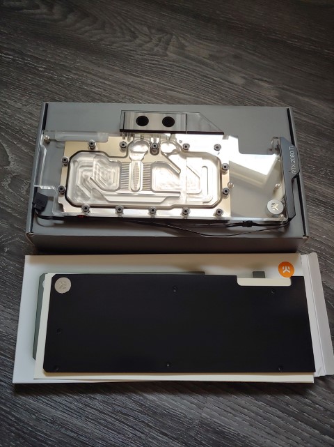
Update #16 April 14, 2019
Just a small update, a few more parts have arrived. I got a nickel-plexi gpu block as well as a black backplate as well as a few fittings and a new multi-port res top.


I have also been stress testing my system over the last few weeks. I managed to get my 9900k to 5.1ghz with a 0.100 offset which makes the cpu peak to 1.376v under full load but for some reason I can’t get all threads prime95 stable there’s always 2 threads that don’t run but it can fold and run RealBench all day long which I guess is good enough for me since I don’t think I will be running prime95 a lot. I don’t plan on running any higher voltage trying to make prime95 stable since it pegs my cpu at 92C and it’s not even summer yet. I also made a pcpartpicker list here: https://ca.pcpartpicker.com/user/NotSoEpicMods/saved/LYysZL
I thought it would be a nice comparison seeing my before and after of my CPU-Z validation. This is how my machine was pretty much ever since 2014 minus adding 2 ssds in raid 0 and to be honest even at that time it was pretty out of date: http://valid.x86.fr/hvspzq and here is my system now: https://valid.x86.fr/1qbv4w which I expect to be “out of date” within 6-12 months. However I do think that this hardware will suit my needs for several years to come or at least until I get the itch to go to something even more extreme.
And before I forget here’s the screen shot of my Cinebench20 run with cpu-z not sure how it stacks up against other 9900k cpus but I think it’s by far better than my 1256 score with my previous cpu.

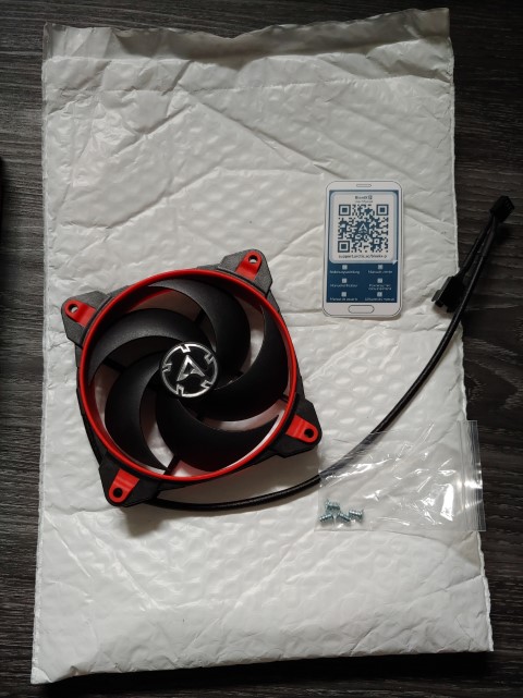
Update #17 April 20, 2019
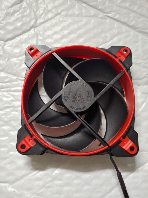
A very minor update bought a new fan to try out think I’ll like it but wanted to try it out first. It’s from Arctic Cooling it has probably the smallest fan motor hub I’ve seen which looks great.


Update #18 May 10, 2019
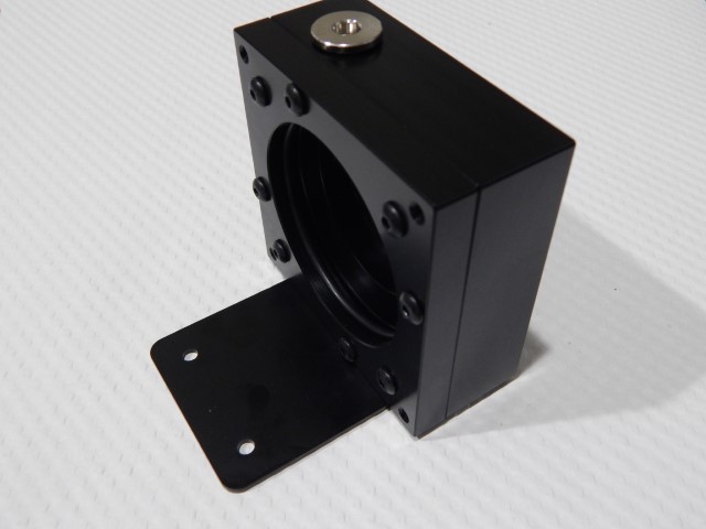
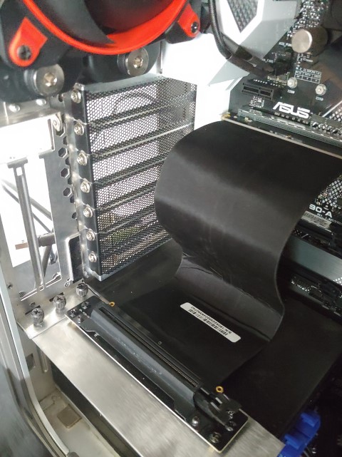
Working on a vertical gpu case mod so show off that sexy 2080ti gpu block once I get it installed. I want to get the vertical mount done before I throw the block on so that I get the proper tubing runs even though they’re flexible. I also got a single 120mm rad for the rear exhaust to be plumbed later with the gpu.

This was my mock up with an old gpu I had. I wanted to make sure the holes and whatnot I’m drilling are in the right spots. The pci slots that will face the back of the case were stolen from an old Shuttle pc that was dismantled long ago and I just cut the section of the case I needed.
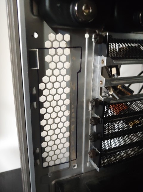
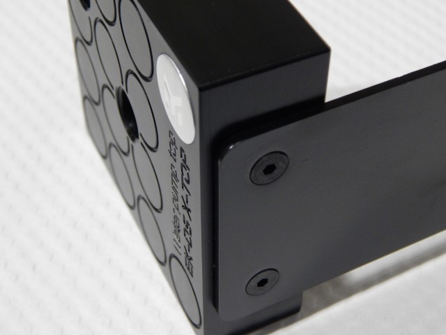
Marker outline is where I’m cutting out the access to the gpu I/O. I already have the mounting holes drilled and I did have to make a reinforcement plate since the aluminum on the Cosmos S and the part from the Shuttle PC were pretty flimsy.
Yes she doesn’t look too pretty but I mean it’s not too bad either and I think once it’s done it’ll look way better. There are 4 screws holding the mount in place and the weight support for the card will be burdened onto the top of the PSU.

Probably the blurriest picture I’ve taken but it’s all I have and I don’t want to crack the case open again and it’s late while I’m writing this. If I was getting paid to do this maybe I would’ve taken another picture. Maybe consider this one of those blurry teaser pictures until I get the gpu block installed.
Update #19 June 10, 2019
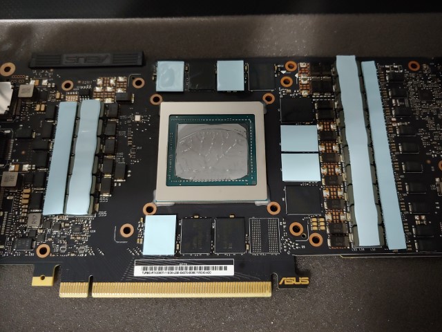
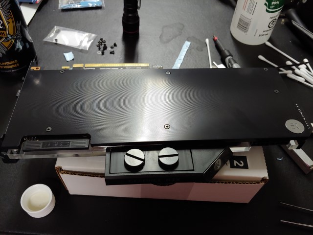
Well today was the big day installing that gpu waterblock. It’s pretty nerve wracking taking apart a gpu you paid $1900 after taxes for especially when you’ve never done anything like it before. Though I was confident going into it doing all my research into getting the right block etc and I dove in head first.


Wow what a beautiful feat of engineering that this card is. I almost wish I could afford a more top tier card but they were all sold out and the ones that were in stock had no waterblocks available from EK at this time. Almost looks like the thermal paste application from factory could’ve been a bit better but I never had temp issues with the stock blower cooler so I guess it was good enough.
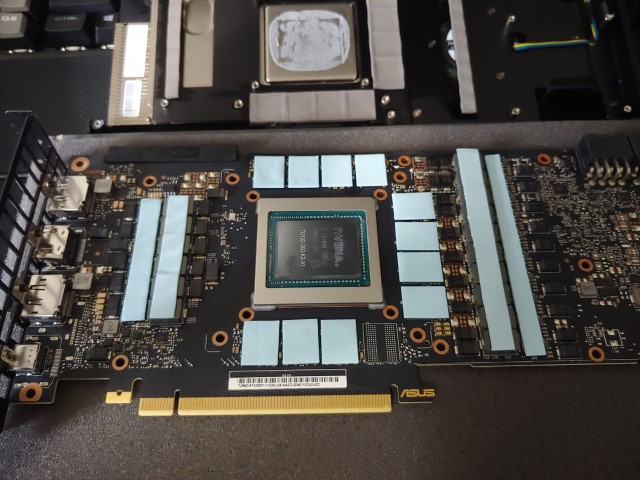
Got that massive gpu die all cleaned of thermal paste and followed the EK instructions and got the thermal pads cut and positioned. Honestly not too hard to do if you’re used to tinkering with stuff.

I also got these Thermaltake flow indicators I’m gonna try out. reviews were mixed about these since some experienced them not spinning while others say they’re great.


Well there it is, waiting for the bubbles to bleed before I test out thermals but hopefully everything is ok.
Update #20 June 11, 2019
Well maybe I spoke too soon. Looks like something I did wasn’t quite right when I installed the gpu block and well I was actually getting worse performance than with the air cooler.
After I tore the block off I found out what had happened, and no it’s not the missing thermal pads in the picture those were still stuck to the block, it was the thermal paste application. As you can see the two corners had no thermal paste on them and it looks like the paste kinda just oozed all the way down to the bottom of the die. All I can think of is uuggghhh. Well I put some Arctic mx-4 thermal paste I had which was quite a bit thicker than the EK provided stuff and well it seemed to improve it greatly and I was able to get much better performance than the stock air cooler. Oh also those Thermaltake flow indicators are kind of a no go since they seem to bind even with some sanding and polishing. Oh well at least it’s up and running properly now. Not sure when the next update will be but stay tuned for that.
Update #21 July 13, 2019
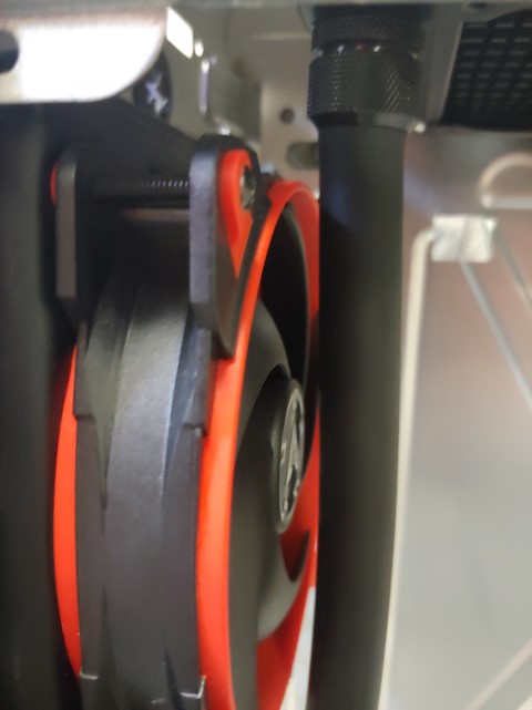
Well the next update came sooner than I thought. I loved that one Arctic cooling Bionix fan so much I went and ordered more.
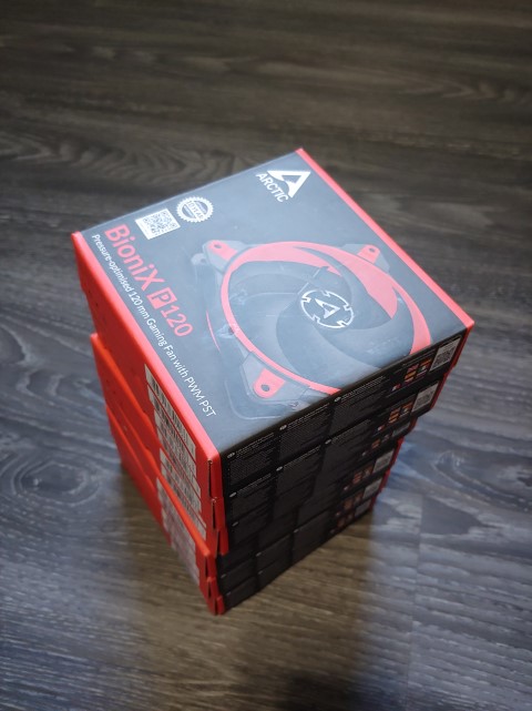

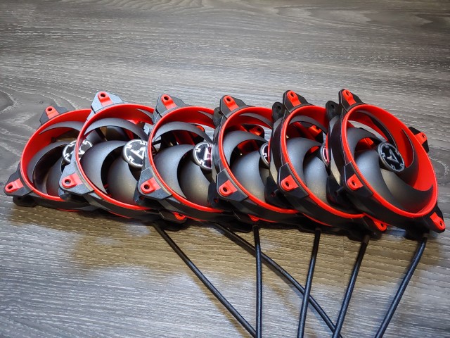
A whole lot more, haha. Got six of them the replace my Cougar and Bitfenix fans. Mmm so many fans.

I also picked up a fan splitter? Powered hub? Idk the thing pictured above to allow one mobo header to control multiple pwm fans.

The old fans for refrence.
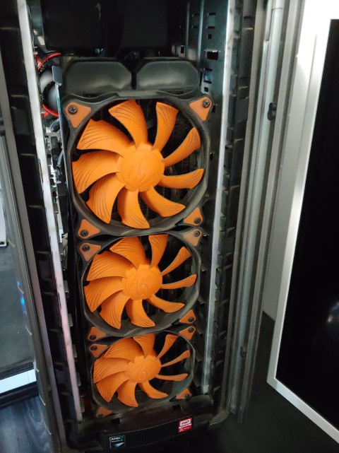
Uhhhhh, eww. Guess even with dust filters that stuff still gets in. Looks like I have to do some vacuuming while the fans are off.

Looks like I’m gonna have to sort out some of this wiring mess also.

Here you can see the difference with the fan motor sizes. Also idk why but I really like the sweeping look of the blades on the Bionix fan, not that it matters since this is a 99% uptime PC.
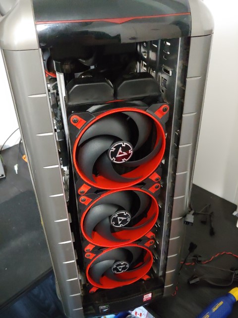

In with the new. Even though you won’t really see them I think they look great.
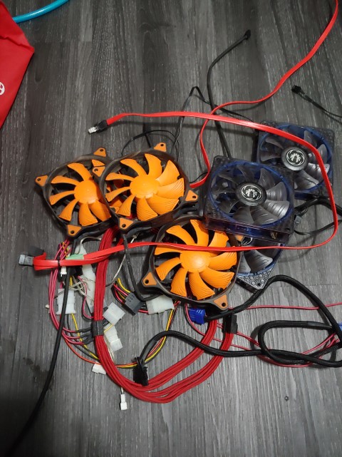
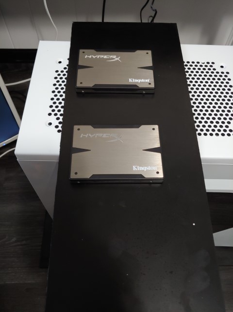
Well here’s everything I’ve ripped out of the case so far for this build. The two ssd will be going into a case (pictured with them) and I’ll reuse the fans in other computers. the cables some of them I’ll toss and some I’ll store away in case I need them. It’s surprising how much clutter in wiring I had in this case.
Update #22 July 24, 2019
Well I got fed up with the onboard fan control on my Asus mobo. Don’t get me wrong it’s adequate for most systems but not what I want in this system. I find the Asus software just doesn’t have the fine control and sensor access that I want. So what do you do? Why spend more money of course *facepalm*
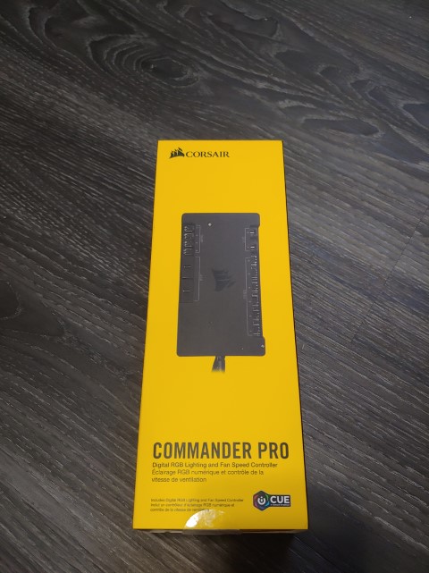
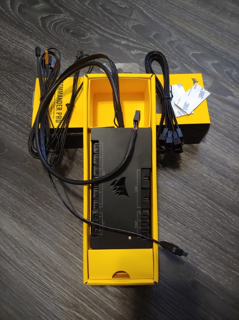
Introducing the commander pro from Corsair. Yea yea you could call me a fanboy since my last and current keyboard and mice as well as my ram are Corsair but hey when a company makes good products you buy em. I’m not sponsored by Corsair or any other company for that matter for this build just fyi. Anyways, the commander pro fits the bill for my uses even though it’s a little on the bulky side. I can hook up my daisy chained rad fans to control and monitor them. I can also just monitor my pump rpm with it as well. There are also 4 temp probes which I plan on having 1 jammed in the vrm heatsink, 1 on the front rad, 1 on the top rad and one for ambient intake air temp. Biggest thing is, I can have iCUE control the fan rpm by the temps of these probes or from the on board sensors of the gpu or cpu.

Well that’s where it will sit in the case for now. Yes I know my wiring is still a horrendous mess back there but no one is really gonna see it. Unfortunately, the temp sensors for the commander pro while yes work great I can’t seem to get attached well enough to the end tanks of my rads. Even with insulating them with lots of electrical tape they still seem to have readings that are off since they read way too close to ambient temp. So I just ended up using the temp directly from the gpu and cpu. Only downside to this is the cpu temp fluctuates a lot +-5 degrees so makes setting the fan curve a little tricky to get my desired slightly positive air pressure.
Update #23 December 24, 2019
Big things are coming.
Update #24 December 24, 2019
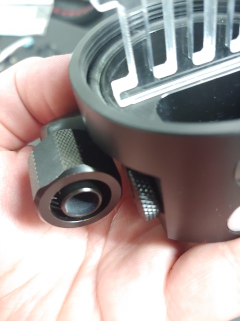
Alright lets get into this. So one of the first things is the new flow meter. While I really like the look of the old ones they were pretty finicky as sometimes the spinning pat would get stuck which I think is lack of a centering pin. Anyways the new one is pretty restrictive so I will be widening the ports on it and polishing the machining on the inside.
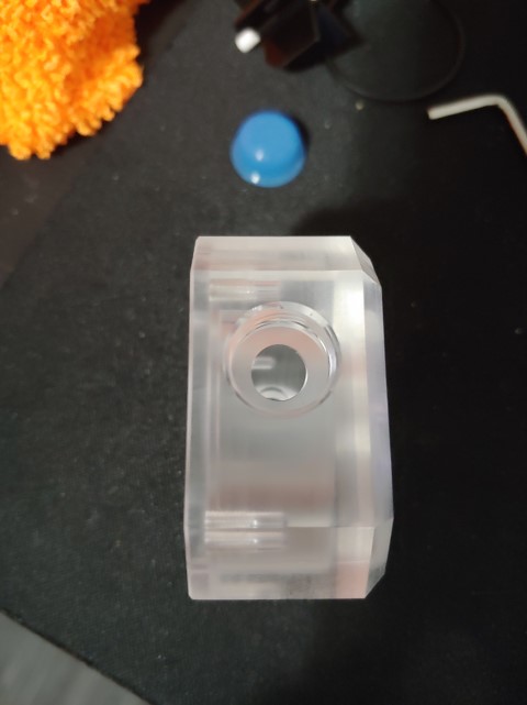
Her you can see how restricted the inlet/outlet is on this flow meter. It makes me a little concerned since I only have a single D5 running this loop which will have 420x30mm rad, 360x60mm rad, 120x30mm rad, gpu block and cpu block.
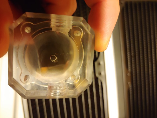
Not the best picture I have of it but how can you take a clear picture of something that is blurry? Anyways as you can see where the impeller sits I have a piece of tubing and you can see how opaque the acrylic is.

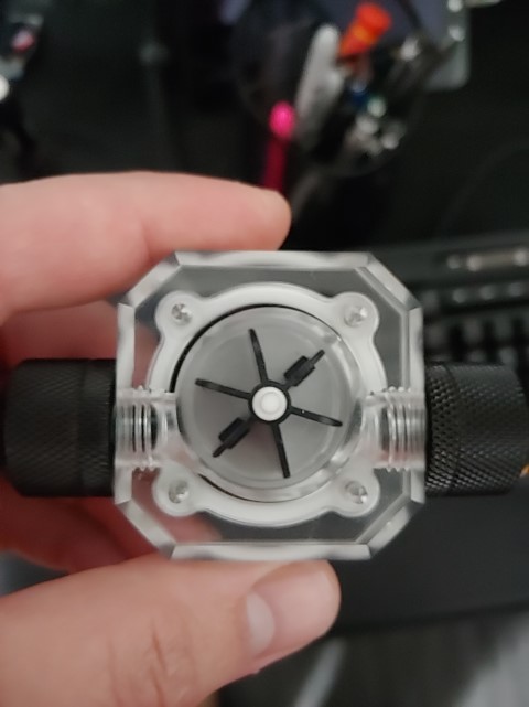
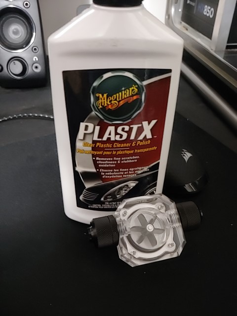
Here’s the finished product. As you can see with the fitting in place there is now no restriction, however I had to be careful as to preserve the flow direction to allow the paddle wheel to spin. I also added a white piece of paper on top of the black pcb for the rpm sensing. Makes the impeller way more visible through that now super clear plexi. I might change the impeller to red later but we’ll see since atm it matches with the white on the motherboard. I also used Meguiar’s PlastX to polish out the machining on the acrylic if you were wondering, it did take a while though.
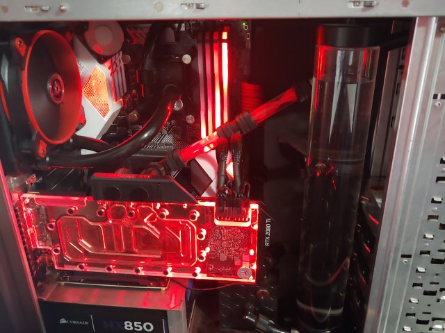
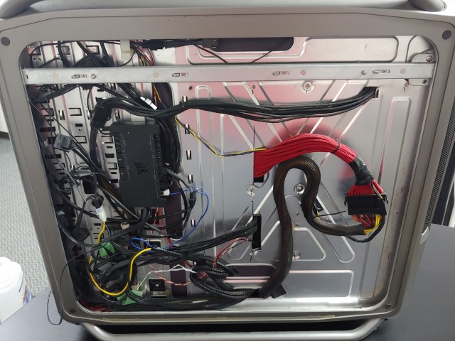
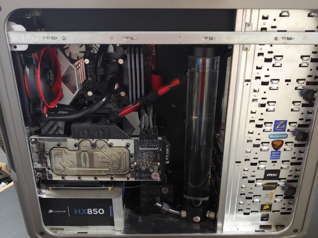
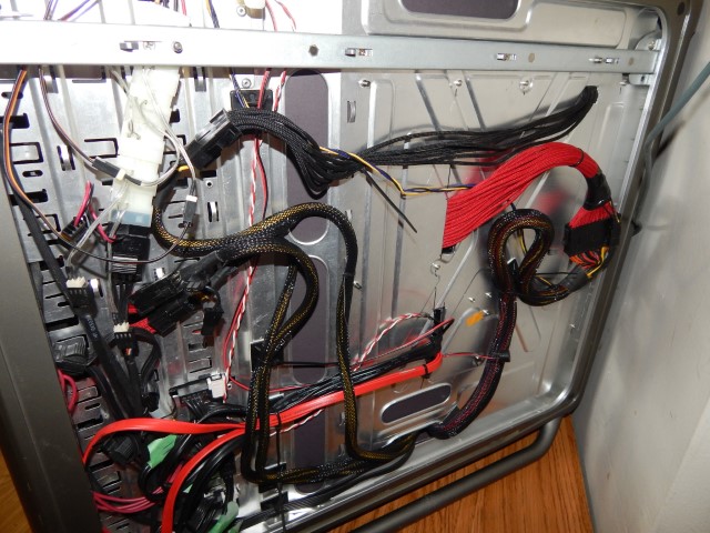
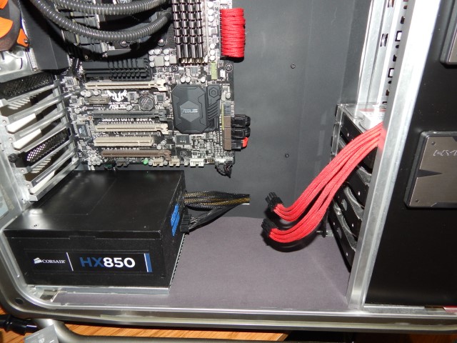
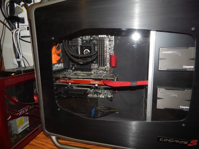
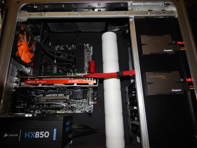
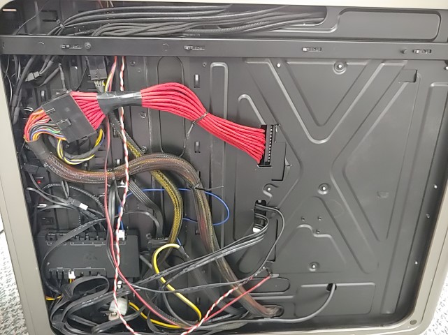
I’m also posting these pictures here as a sort of before and after reference I don’t expect the rear cable management to improve drastically but I’m aiming for the front to look clean. I’ll be dismantling it later tonight and hope to have another post ready for Christmas day.
Update #25 December 25, 2019
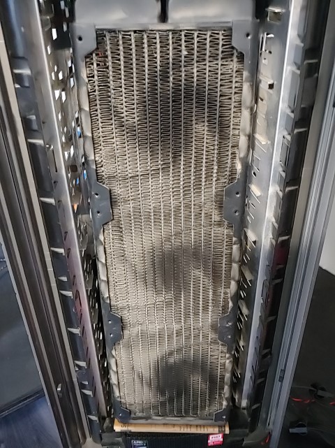
Alright here we go. So I spent some time tearing apart the system, man this thing was dusty.

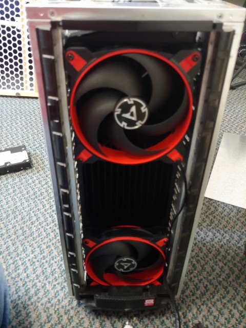
Well here’s the front of the case with all the mesh taken off. The current rad in there is a 3x120mm Darkside and from my initial parts picture you’re probably thinking oh well he’s just swapping out to a cross flow rad for better tubing runs. Well what might have been hard to see in my parts picture is that the 30mm thick rad is actually a 3x140mm rad which I’m going to “finesse” into the front of this case. I did measuring and well it’s going to be a little tight.

Blegh, even though I did vacuum this a few months ago it still looks horrible in this lighting.
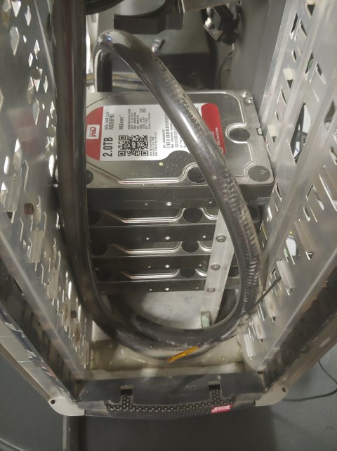
Well don’t ask me why I used such long tubing runs cus I don’t know either. It might of been a combination of first time custom water cooling and my impatience. This is also how I had my hard drives mounted because apparently they would kinda fit length wise in the 5.25″ bay. I wouldn’t recommend doing this though. Well that’s it for this update the rest of the disassembly is pretty boring and standard.
Update #26 December 28, 2019
Ok so the case is apart and I’m doing some test fitting for that front rad. First thing first is to smash down those 5.25″ drive bay support tabs.

One nice thing about the case being aluminum is that it’s really easy to bent those tabs. After getting all the tabs flattened it was time to see if the rad fits and with my measurements it, should?

Well, it fits, kinda. Oof those clearances are almost too tight for comfort. The side to side clearance is tight enough to securely hold the rad in place and the top clearance with the rad sitting on the bottom of the case is about 5mm. The bottom fan will only be held in with the top 2 screws and looses a little air flow on the bottom portion but honestly it’s only like 2mm. Reason for only the 2 screws on the bottom fan is that this front rad will not move up and down enough to expose the screws and the entire case has to be disassembled to remove the screws. That or a good portion of the internals including the top rad will have to be removed, speaking of which…
Test fitting the rear fitting of the top rad and the rear fan/rad combo. It has slightly better clearances.

Well I’ll leave you with this water flow chart I came up with and which is why I purchased new cross flow rads. One of my main goals with this upgrade is the simplification of the water cooling system and trying to eliminate unneeded/unwanted tubing runs. Let me know what you think, both of my plans and my MS paint skills haha.
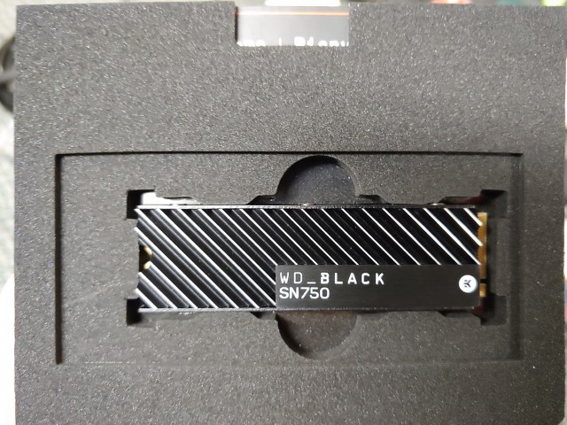
Not really an update so I’ll just tack this onto here. I should be receiving my Christmas gift to myself tomorrow and let’s just say my wallet is still recovering and will be recovering for a long while. I might have overpaid for it but that heatsink just looks so classy. Will be posting some pics when I get it.

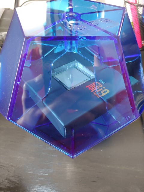
Update #27 December 29, 2019
Well my drive came in and wow, in person, it looks real slick. Was it worth the price I paid? Again, probably not.

Remounted the CPU block with the Phobya flow through temp sensor fitting on the exit side.
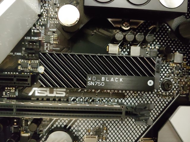
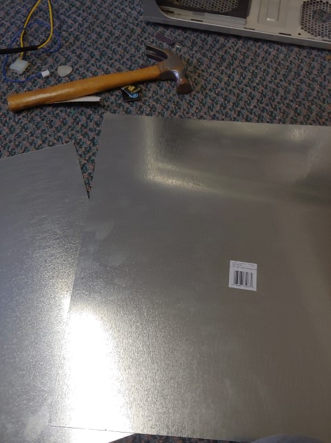
While I was at it I threw in that smexy NVMe drive. There’s also no doubt that I’m going to have to do some sheet metal work for the interior of the case. I just used some very thin galvanized ducting for ease of use.

With the 2 NVMe ssds now in the system I no longer need 4 hard drives, plus I plan on having some sort of NAS at some point. So I will be retaining my two WD Red drives and moving my WD Black and Green to other PCs. I also decided to try something new and as you can see this is how I’m planning on displaying those drives. I used mobo stand offs I had to space them from the case.
Here’s a better look at how things will sit inside the case. If you noticed I cut out a large portion of the 5.25″ bay mounting area. I may or may not regret this at some point in the far future since this is such a classic pc case but we’ll see. I was also planning on making a cut out for the cpu back plate but after thinking for a little bit I honestly don’t think I would ever change my cpu block or cooler enough to justify cutting one. I also I only made necessary cut outs for the 24 pin, sata data, and front panel connectors.
After I got everything mocked up I walked by my box of random pc junk and this 2.5″ to 3.5″ drive adapter that I got with my old ssds long ago caught my eye. It looks just tall enough for something…

Perfect, looks like I can add another drive haha.
Well this is everything I will need to paint. Mobo tray cover, 2.5″ drive bracket, new case floor, vertical gpu bracket and the case itself. I’ll be using a matte black automotive wheel paint once I get all the surfaces prepped tonight.
Update #28 December 30, 2019
Well parts are painted.
While I was waiting between coats and the paint to dry I decided to tackle my gpu. If you didn’t know when I first installed my full cover block I had temp issues. After a remount the temp issues improved but I never really got quite the performance and temperatures I was expecting even though I did buy a lower tier 2080Ti.

So I decided to crack this thing open since I have the entire system apart anyways. I also want to clean the block since I had some residue in my old loop which seems to have collected in the gpu block. This is also kind of the reason I went with a clear block instead of a solid acetal block like my cpu is so that I can easily see if the system needs any maintenance.
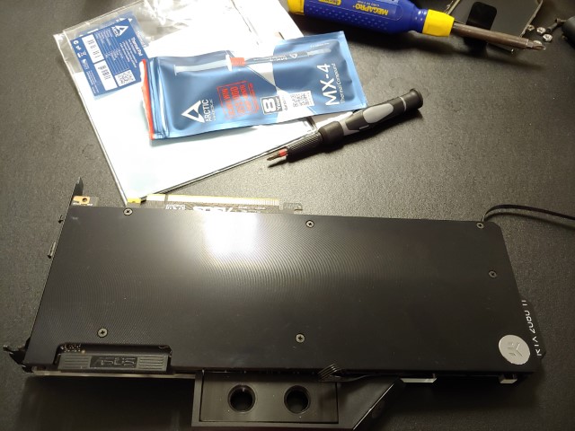
I also purchased new Arctic MX-4 thermal paste and Arctic thermal pads to replace what I had already on the card.

Well that thermal spread looks pretty crap. No wonder my temps weren’t that great and my boost clock wasn’t nearly as high as I wanted. While it was a better spread than my last attempt it still wasn’t great so it got me thinking what the hell. Then I noticed it, if you look at the mounting holes around the die you’ll notice that there’s some squished glue on them. It was like a light bulb turned on and I couldn’t believe I didn’t see it before. So I very very very carefully took a box cutter and scraped away all the glue I could.


Well I wiped the block clean and got all the thermal pads applied and applied thermal paste. I probably didn’t need the 4 dots since the center of the X was fairly thick but since it’s non conductive paste I figured it won’t hurt. I also filed the parts of the mounting posts on the block that face the corners of gpu die.
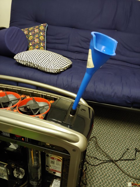
I also began prepping all the other parts including the pump and res. I probably should’ve checked clearances like this 90 on the res earlier since I want to get the pc up and running for new years but I guess it worked out.
Update #29 December 31, 2019
So all the best plans can always have some hiccups.

The 90 I was planning on using, the one coming out of the rad in the picture above, turns out was leaking quite a bit. It was one of those re-branded type fittings and is the second that has leaked on me which is why I never really used them for critical points in the loop like over a gpu. So time for a redesign.


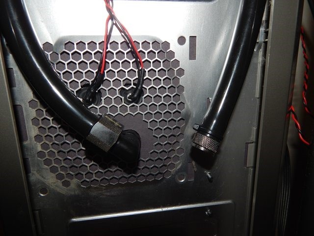
Yep that’ll work. I guess the paint isn’t fully cured yet either since some of it has flaked off from the plastic clips. I ended up drilling another hole on the other side of the case and just ran a tube through it cus really who’s gonna lift my system just to check how my drain port works.
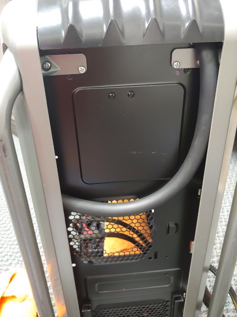
This is how the tube will be stored under the case so it’ll be totally stealthed. I don’t have a drain valve just a plugged fitting. My plan is to just pinch off the hose then pull plug out to drain the system. It’s worked fine for me in the past so why make it more complicated?
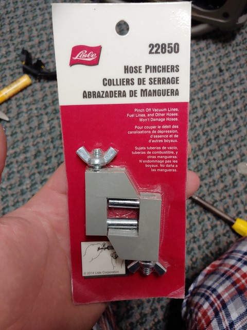
Plus these only cost a couple dollars anyways and they don’t damage the hose.
Before getting the drives and res in I put some black car edge trim over the jagged parts that I cut away. That hose coming from the top is actually coming from the fill port and not the top of the rads. The way I connected the 2 rads together is probably the tightest tubing run I’ve ever seen/done I’ll put a pic below.
That is about 3/4″ space between the fittings and they’re offset so that makes it even more challenging to get installed properly.

All parts are in. Now I know what you’re thinking. why in the world would you put a 2.5″ 5400rpm hard drive in this system? Well, I actually have an ssd on the way and a family member will be bringing it tonight for New Years when they visit.
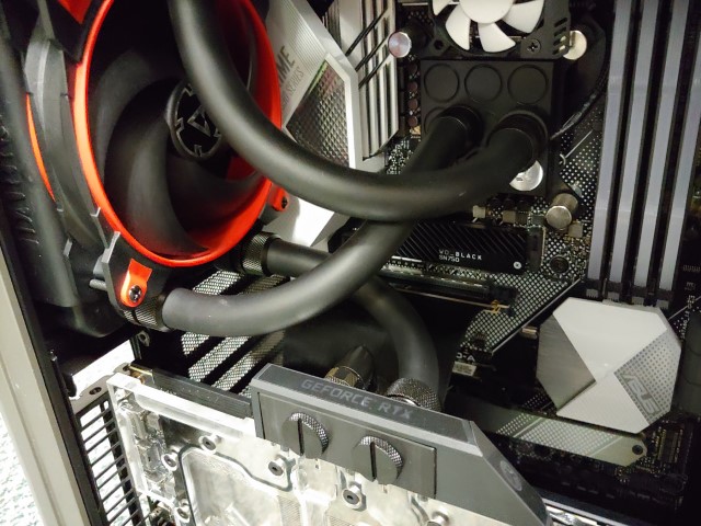
This is my tube routing, it’s as short as I can get the tubing runs but I’m not 100% sure about the layout. None of the tubes really cross too much. I’m not even sure how else I could change it. But I really love that EK matte black tubing. Again my loop routing is Res>Pump>GPU>Rear Rad>CPU>Top Rad>Front Rad then back to res.
Pretty easy to fill this loop. You may also notice that there’s no front I/O and well since I removed it 5 years ago I haven’t missed it at all. At my last place I actually had a USB extension mounted to the underside of my desk which is really all I needed for this pc. Now I have a usb port on my keyboard so I don’t even need the under desk usb port.
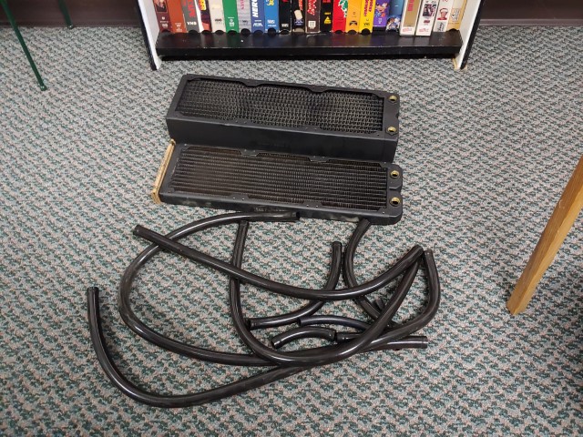
Holy crap I don’t know why I had so much tubing before especially since I only had the cpu to cool. Anyways, here’s all the old tubing which I will keep most of for just in case and other stuff and the 2 old rads.
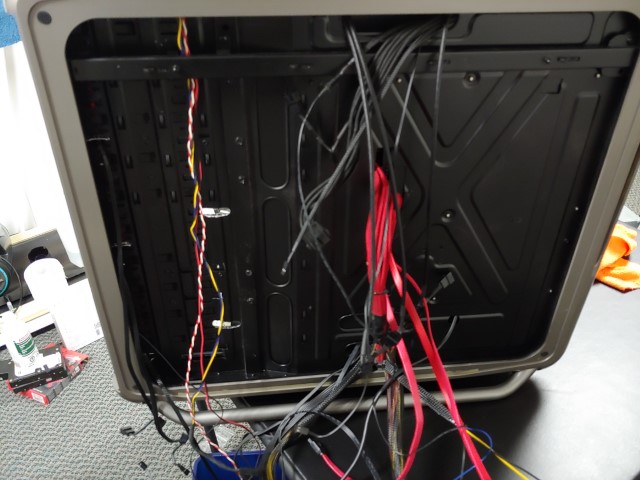
Sorting through the mess of wires while I bleed the bubbles out of the loop.
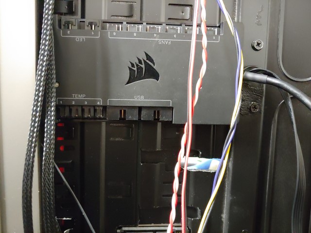
The almighty commander pro. Surprisingly one of my favorite purchases for my pc. While it’s not perfect it does pretty much what I need it to do. It’ll also work with my 2 Phobya in line temp sensors. It also adds 2 usb headers behind the mobo tray if I want to add things later.
Well she ain’t pretty at the back but she works.

But aww man look at that front. Does it ever look clean. What do you think?
Transferring the files off the old hard drive onto the new WD NVMe.

Well until I get my SSD I’m gonna hold off on doing glamour pics. I also have a new mic for my setup which I’ll probably do a whole setup picture as well.


You post very interesting posts here. Your website deserves much more traffic.
It can go viral if you give it initial boost, i know very useful service that
can help you, simply search in google: svetsern traffic tips
LikeLike